Digital and Analog Inputs and Outputs
13-16
13
-
Programming Off:
when this function is programmed and the digital input is with +24 V, parameter changes
will not be allowed, regardless of the values set at P0000 and P0200. When the DIx input is with 0 V, the
parameter changes will be conditioned to the P0000 and P0200 settings.
-
DO2 and DO3 Timer:
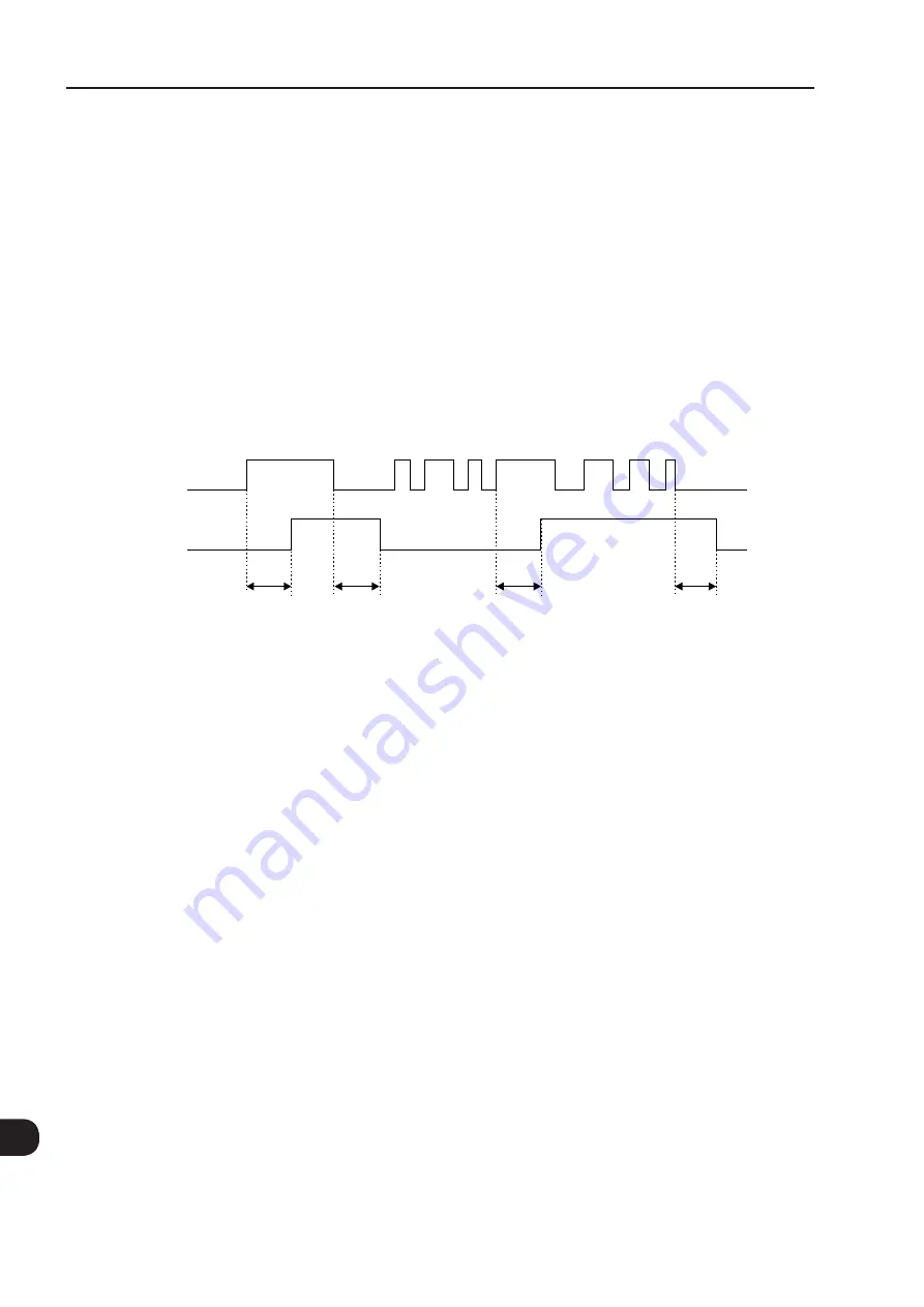
this function acts as a timer to activate and deactivate the relays 2 and 3 (DO2 and
DO3).
When the timer function for the relay 2 or 3 is programmed at any DIx, and a transition from 0 V to +24 V occurs, the
programmed relay will be activated with the delay set in P0283 (DO2) or P0285 (DO3). When a transition from +24
V to 0 V occurs, the programmed relay will be deactivated with the delay adjusted in P0284 (DO2) or P0286 (DO3).
After the transition of the DIx, either for activating or deactivating the programmed relay, it is necessary that the DIx
remains in ON or OFF during at least the time set in P0283/P0285 or P0284/P0286. Otherwise the timer will be
reset. Refer to the
Note:
In order to enable that function it is also necessary to program P0276 and/or P0277 = 29 (Timer).
+24 V
0 V
DIx
DO2 (RL2)
DO3 (RL3)
ON
OFF
P0283/P0285
P0284/P0286
P0283/P0285
P0284/P0286
Figure 13.5 -
Operation of the timer function DO2 (RL2) and DO3 (RL3)
-
Multispeed:
the setting of the parameters P0266 and/or P0267 and/or P0268 = 13 requires that the parameters
P0221 and/or P0222 be programmed in 8. Refer to the description of the parameters P0124 to P0131 in the
Section 12.4 MULTISPEED [36] on page 12-7
-
Trace Function:
it triggers the data acquisition at the channels selected with that function, when the three
following conditions were fulfilled:
- If the DIx is with 24 V.
- Trigger condition set in P0552 = 6 "DIx".
- Function waiting for the trigger, P0576 = 1 "Waiting".
Chapter 19 TRACE FUNCTION [52] on page 19-1
-
No External Alarm:
This function will indicate "External Alarm" (A090) on the keypad (HMI) display when the
programmed digital input is open (0 V). If +24 V is applied to the input, the alarm message will disappear automatically
from the keypad (HMI) display. The motor keeps working normally, regardless of the state of that input.
- Manual/Automatic:
It allows selecting the CFW-11 speed reference between the reference defined by P0221/P0222
(Manual mode – DIx open) and the reference defined by the PID regulator (Automatic mode – DIx with 24 V).
Refer to the
Chapter 20 PID REGULATOR [46] on page 20-1
- PLC use:
When this option is selected it will not take any action for the CFW-11. It can be used as a remote
input for the PLC11 board or for communication networks.
Summary of Contents for CFW-11 Series
Page 2: ......
Page 54: ...2 4 2 General Information ...
Page 58: ...About the CFW 11 3 3 4 ...
Page 74: ...Inverter Model and Accessories Identification 5 14 6 ...
Page 86: ...Inverter Model and Accessories Identification 6 12 6 ...
Page 94: ...Available Control Types 8 2 8 ...
Page 118: ...VVW Control 10 8 10 ...
Page 182: ...Functions Common to All the Control Modes 12 26 12 ...
Page 220: ...Dynamic Braking 14 4 14 ...


