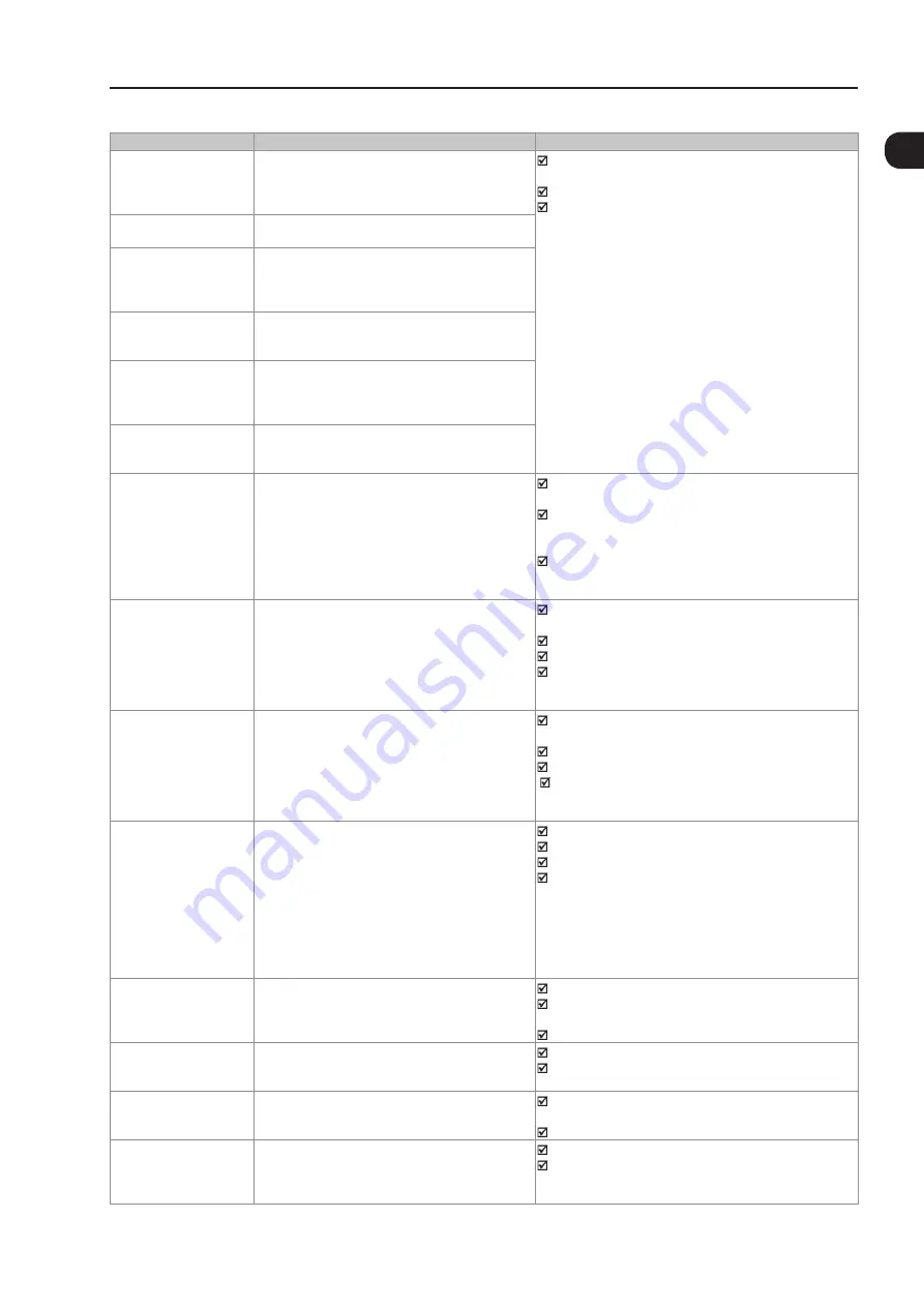
Quick Parameter Reference, Faults and Alarms
0-31
0
Fault/Alarm
Description
Possible Causes
A050
(1)
IGBT High Temperature U
A high temperature alarm was detected by the NTC
temperature sensors located on the IGBTs.
Note:
It may be disabled by setting P0353 = 2 or 3.
Surrounding air temperature is too high (>50 °C (122 °F))
and output current is too high.
Blocked or defective fan.
Very dirty heatsink.
F051
(1)
IGBT Overtemperature U
A high temperature fault was detected by the NTC
temperature sensors located on the IGBTs.
A053
(12)
High Temperature on
IGBTs V
Alarm of high temperature measured at the
temperature sensors (NTC) of the IGBTs.
Note:
It can be disabled by setting P0353 = 2 or 3.
F054
(12)
Overtemperature on
IGBTs V
Fault of overtemperature measured at the
temperature sensors (NTC) of the IGBTs.
A056
(12)
High Temperature on
IGBTs W
Alarm of high temperature measured at the
temperature sensors (NTC) of the IGBTs.
Note:
It can be disabled by setting P0353 = 2 or 3.
F057
(12)
Overtemperature on
IGBTs W
Fault of overtemperature measured at the
temperature sensors (NTC) of the IGBTs.
F062
(15)
Thermal Imbalance
Fault of power module temperature imbalance.
The temperature difference between IGBT modules of the
same phase (U, V, W) was above 15 °C (59 ° F).
The temperature difference between IGBT modules of
different phases (U and V, U and W, V and W) was above
20 °C (68 ° F).
The temperature difference between rectifier modules of
different phases (R and S, R and T, S and T) was above
20 °C (68 ° F).
F065
Encoder Signal Fault (SW)
Feedback obtained via encoder does not match the
commanded speed.
The fault can be disabled via parameter P0358
Wiring between encoder and encoder interface accessory
interrupted.
Encoder is defective.
Encoder coupling to the motor is broken.
Inverter operating in current limit (In case the application
needs to run in such condition, this fault should be
disabled via parameter P0358).
F066
Encoder Signal Fault (SW)
Feedback obtained via encoder does not match the
commanded speed.
The fault can be disabled via parameter P0358
Wiring between encoder and encoder interface accessory
interrupted.
Encoder is defective.
Encoder coupling to the motor is broken.
I nverter operating in current limit (In case the application
needs to run in such condition, this fault should be
disabled via parameter P0358).
F067
Incorrect Encoder/
Motor Wiring
Fault related to the phase relation of the encoder
signals, if P0202 = 4 and P0408 = 0, 2, 3 or 4.
Note:
- It is not possible to reset this fault (when P0408>1).
- In this case, turn off the power supply, solve the
problem, and then turn it on again.
- When P0408 = 0, it is possible to reset this fault.
This fault could be disabled by means of parameter
P0358.
In this case it is possible to reset this fault.
Output motor cables U, V, W are inverted.
Encoder channels A and B are inverted.
Encoder was not properly mounted.
Motor with locked rotor or dragging at the start.
F070
(4)
Overcurrent /
Short-circuit
Overcurrent or short-circuit detected at the output,
in the DC bus, or at the braking resistor.
Short-circuit between two motor phases.
Short-circuit between the connection cables of the
dynamic braking resistor.
IGBT modules are shorted.
F071
Output Overcurrent
The inverter output current was too high for too long.
Excessive load inertia or acceleration time too short.
Settings of P0135 or P0169, P0170, P0171, and P0172
are too high.
F072
Motor Overload
The motor overload protection operated.
Note:
It may be disabled by setting P0348 = 0 or 3.
Settings of P0156, P0157, and P0158 are too low for the
used motor.
Motor shaft load is excessive.
F074
Ground Fault
A ground fault occured either in the cable between
the inverter and the motor or in the motor itself.
Note:
It may be disabled by setting P0343 = 0.
Shorted wiring in one or more of the output phases.
Motor cable capacitance is too large, resulting in current
peaks at the output.
(14)
Summary of Contents for CFW-11 Series
Page 2: ......
Page 54: ...2 4 2 General Information ...
Page 58: ...About the CFW 11 3 3 4 ...
Page 74: ...Inverter Model and Accessories Identification 5 14 6 ...
Page 86: ...Inverter Model and Accessories Identification 6 12 6 ...
Page 94: ...Available Control Types 8 2 8 ...
Page 118: ...VVW Control 10 8 10 ...
Page 182: ...Functions Common to All the Control Modes 12 26 12 ...
Page 220: ...Dynamic Braking 14 4 14 ...


