3
CFW-11M RB |3-23
Installation and Connection
3.4.6 UC11 Connections
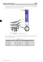
The DIM1 and DIM2 digital inputs located on the IPS1 board (Figure 3.32 and 3.34) monitor F408 and
F410 faults. They are CLOSED when running in normal operation and they are OPEN when the converter
is under any fault condition.
- The DIM1 digital input is connected at XC1:4 and XC1:5 (common).
- The DIM2 digital input is connected at XC2:4 and XC2:5 (common).
XC1
Factory Default Function
Specifications
1
No Function
-
-
2
No Function
-
-
3
DGND
DGND Reference.
Grounded via the IPS board shield.
4
DIM1
Isolated digital input DIM1,
programmable at P0832. Refer
to the programming manual.
High level ≥ 18 V.
Low level ≤ 3 V.
Maximum input voltage: 30 V.
Input current: 11 mA @ 24 Vdc.
5
COM
Common point of the IPS board
digital inputs.
XC2
Factory Default Function
Specifications
1
No Function
-
-
2
No Function
-
-
3
DGND
DGND Reference.
Grounded via the IPS board shield.
4
DIM2
Isolated digital input DIM2,
programmable at P0833. Refer
to the programming manual.
High level ≥ 18 V.
Low level ≤ 3 V.
Maximum input voltage: 30 V.
Input current: 11 mA @ 24 Vdc.
5
COM
Common point of the IPS board
digital inputs.
XC3
Factory Default Function
Specifications
1
PCR1 (NO)
RL digital output with pre-charge
function (PCR).
Contact capacity: 1 A.
Maximum voltage: 240 Vac.
NO - Normally open contact.
C - Common.
NC - Normally closed contact.
2
PCR2 (C)
3
PCR3 (NC)
4
GND_24
0 V reference for the 24 Vdc
power supply.
Isolated power supply: 24 Vdc ± 8 %.
Capacity: 600 mA.
Note 1:
This power supply may be used for
feeding the IPS board digital inputs DIM1
(ISOL) and DIM2 (ISOL).
Note 2:
This power supply is isolated from
the 24 Vdc input used to feed the IPS.
5
+24 V
24 Vdc power supply.
Figure 3.31 -
Application example with high level at the DIs
Table 3.10 -
Functions of the digital inputs
Parameters
Sequential
Number
Digital Input Function
Associated
Fault/Alarm
P0832/P0833
0
Not Used
-
1
Extern Fault
F410
2
Refrigeration Fault
F408


