3
CFW-11M RB |3-29
Installation and Connection
Synchronism
transformer
Re
gener
at
iv
e c
on
ver
ter
Lo
w v
ol
ta
ge p
ow
er s
up
pl
y
In
ver
ter
Motor
L1
L2
DC Link
UC11
UC11-RB
R
S
T
U V W
Filter 2
R
T
R
S
R
R
C
R
C
S
C
T
A
B
C
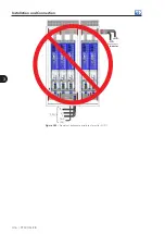
Figure 3.43 -
Simplified connection drawing of the filter 2 with two power units
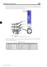
3.4.7.5 Filter Type Selection
The
filter 2
should be used whenever it is possible because it prevents high-frequency currents flow on the
main power supply eliminating potential interference with other equipment.
The
filter 1
can be used only when some specific conditions are met, as stated in the figure 3.44:
Type of
filter
Yes
Yes
No
No
Use filter 2
Filter 1
can be used
Is the
transformer power rating
bigger than 20 times the motor
power rating?
Are there any other
load (equipment) connected to the
same transformer?
Figure 3.44 -
Filter type selection flowchart


