4
CFW-11M RB |4-3
Keypad and Display
;
The HMI can be installed or removed from the converter with or without AC power applied to the converter.
;
The HMI supplied with the product can also be used for remote command of the converter. In this case,
use a cable with male and female D-Sub9 (DB-9) connectors wired pin to pin (mouse extension type)
or a market standard Null-Modem cable. Maximum cable length: 10 m (33 ft). It is recommended the
use of the M3 x 5.8 standoffs supplied with the product. Recommended torque: 0.5 N.m (4.5 lbf.in).
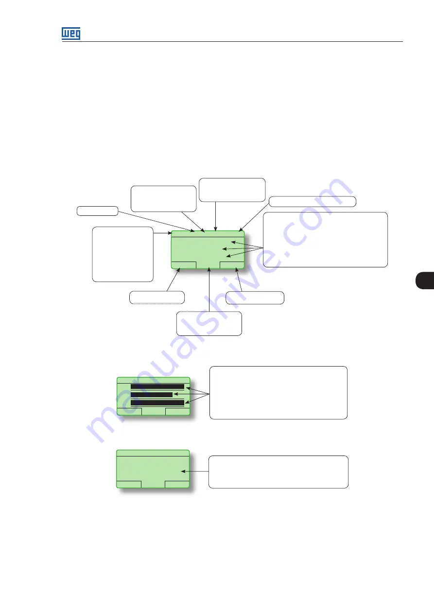
When power is applied to the converter, the display automatically enters the monitoring mode. Figure 4.3
(a)
presents the monitoring screen displayed for the factory default settings. By properly setting specific converter
parameters, other variables can be displayed in the monitoring mode or the value of a parameter can be
displayed using bar graphs or with larger characters as presented in figures 4.3
(b)
and
(c)
.
Control mode indication:
LOC: local mode.
REM: remote mode.
Clock
Settings via:
P0197, P0198, and P0199.
Run
RB + LOC 618V
12:35
Menu
400
A
618
V
380
V
DC link voltage (Volts).
Monitoring parameters:
- Input current (Amps).
- DC link voltage (Volts).
- Line voltage (Volts) (P0002).
P0205, P0206 and P0207: selection of parameters
that will be displayed in the monitoring mode.
Right soft key feature.
Left soft key feature.
Converter status:
- Run.
- Ready.
- Config.
- Last fault: FXXX.
- Last alarm: AXXX.
- etc.
Active power:
+ Motorizing.
- Regenerating.
RB Control.
(a) Monitoring screen with factory default settings
Run
RB + LOC 618 V
12:35
Menu
Monitoring parameters:
- Input current.
- DC link voltage.
- Line voltage (Volts) (P0002).
P0205, P0206 and P0207: selection of parameters
that will be displayed in the monitoring mode.
100%
77%
A
V
V
100%
(b) Example of a monitoring screen with bar ghaphs
Run
RB + LOC 618V
12:35
Menu
400
Value of one of the parameters defined in P0205,
P0206, or P0207 displayed with a larger font size.
Set parameters P0205, P0206 or P0207 to 0 if it is
not desirable to display them.
A
(c) Example of a monitoring screen displaying a parameter with a larger font size
Figure 4.3 -
(a) to (c) Monitoring modes
4.2 PARAMETERS ORGANIZATION
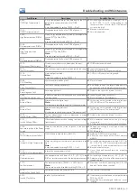
When the right soft key ("MENU") is pressed in the monitoring mode, the display shows the first 4 groups of
parameters. Table 4.1 shows an example of parameter groups and how they are organized. The number


