Functions Common to All the Control Modes
CFW500 | 11-7
11
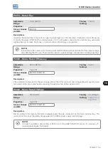
P0135 – Maximum Output Current
Adjustable
Range:
0.0 to 200.0 A
Factory
Setting:
1.5 x I
nom
Properties:
Access Groups
via HMI:
BASIC, MOTOR
Description:
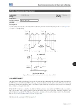
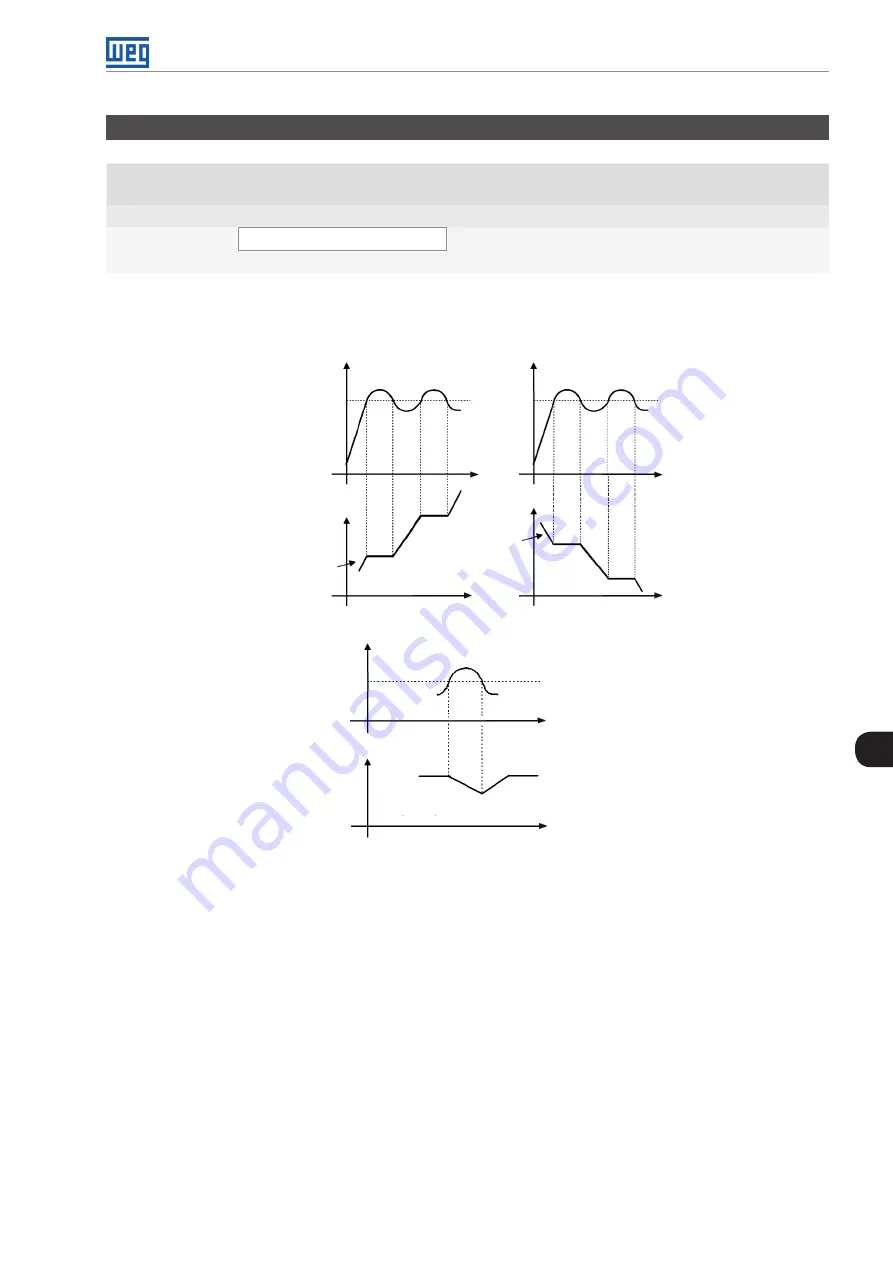
Current level to activate the current limitation for the Ramp Hold and Decelerate Ramp modes, as per
, respectively.
t(s)
t(s)
t(s)
t(s)
Acceleration
Ramp
acceleration
(P0100)
Ramp
deceleration
(P0101)
Deceleration
(a) "Ramp Hold"
Output
frequency
Motor
current
P0135
Motor
current
P0135
t(s)
t(s)
Ramp
deceleration
(P0101)
(b) "Ramp Deceleration"
Motor
current
P0135
Output
frequency
Figure 11.6:
(a) and (b) Actuation modes of Current Limitation via P0135
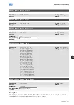
11.3 SLEEP MODE
The Sleep mode allows the inverter to turn off the motor when the speed reference is below the value programmed
in P0217 for a period defined by P0218. In this way, the speed reference itself is able to turn off the motor, reducing
the energy consumption. Besides, there is no need of digital command to drive the motor, that is, the reference
also actuates as a logical command.
When the PID controller is active, the condition for the Sleep mode is incremented by P0535, besides parameters
P0217 and P0218. This condition adds a minimum deviation criterion of the process variable in relation to the
setpoint (error), ensuring that the PID keeps the process variable control over the Sleep mode. For further details,
refer to
Section 13.3 SLEEP MODE WITH PID on page 13-6
.
The Sleep mode is signaled in P0006 equal to 7.
Summary of Contents for CFW500 V1.8X
Page 2: ......
Page 4: ......
Page 8: ...Contents...
Page 34: ...General Information 2 4 CFW500...
Page 38: ...About the CFW500 3 4 CFW500 3...
Page 42: ...HMI and Basic Programming 4 4 CFW500 4...
Page 52: ...Programming Basic Instructions 5 10 CFW500 5...
Page 56: ...Identification of the Inverter Model and Accessories 6 4 CFW500 6...
Page 76: ...Available Motor Control Types 8 4 CFW500 8...
Page 84: ...V f Scalar Control 9 8 CFW500 9...
Page 170: ...Communication 17 8 CFW500 17...


