Digital and Analog Inputs and Outputs
12-14 | CFW500
12
P0258 – Frequency Output Gain FO
Adjustable
Range:
0.000 to 9.999
Factory
Setting:
1.000
P0259 – Minimum Frequency Output FO
Adjustable
Range:
10 to 20000 Hz
Factory
Setting:
10 Hz
P0260 – Maximum Frequency Output FO
Adjustable
Range:
10 to 20000 Hz
Factory
Setting:
10000 Hz
Properties:
Access Groups
via HMI:
I/O
Description:
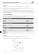
Gain, minimum and maximum values for frequency output FO.
12.5 DIGITAL INPUTS
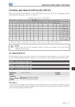
In order to use the digital inputs, the CFW500 features up to eight ports, depending on the plug-in module
connected to the product. Check
.
Below are described the parameters for digital inputs.
P0271 – Digital Input Signal
Adjustable
Range:
0 = All DIx are NPN
1 = (DI1) - PNP
2 = (DI1...DI2) - PNP
3 = (DI1...DI3) - PNP
4 = (DI1...DI4) - PNP
5 = (DI1...DI5) - PNP
6 = (DI1...DI6) - PNP
7 = (DI1...DI7) - PNP
8 = All DIx are PNP
Factory
Setting:
0
Properties:
cfg
Access Groups
via HMI:
I/O
Description:
It configures the default for the digital input signal, that is, NPN and the digital input is activated with 0 V, PNP
and the digital input is activated with +24 V.
Summary of Contents for CFW500 V1.8X
Page 2: ......
Page 4: ......
Page 8: ...Contents...
Page 34: ...General Information 2 4 CFW500...
Page 38: ...About the CFW500 3 4 CFW500 3...
Page 42: ...HMI and Basic Programming 4 4 CFW500 4...
Page 52: ...Programming Basic Instructions 5 10 CFW500 5...
Page 56: ...Identification of the Inverter Model and Accessories 6 4 CFW500 6...
Page 76: ...Available Motor Control Types 8 4 CFW500 8...
Page 84: ...V f Scalar Control 9 8 CFW500 9...
Page 170: ...Communication 17 8 CFW500 17...


