2
General Information
CFW500 | 2-1
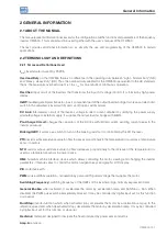
2 GENERAL INFORMATION
2.1 ABOUT THE MANUAL
This manual presents information necessary for the configuration of all the functions and parameters of the frequency
inverter CFW500. This manual must be used together with the user’s manual of the CFW500.
The text provides additional information so as simplify the use and programming of the CFW500 in certain
applications.
2.2 TERMINOLOGY AND DEFINITIONS
2.2.1 Terms and Definitions Used
I
nom
:
inverter rated current by P0295.
Overload Duty:
in the CFW500 there is no difference in the operating duty between “Light - Normal Duty” (ND)
and “Heavy - Heavy Duty” (HD). Thus, the overload duty adopted for the CFW500 is equivalent to the HD standard,
that is, the maximum overload current is 1.5 x I
nom
for one minute of continuous operation.
Rectifier:
input circuit of the inverters that transforms the input AC voltage into DC. It is formed by high-power
diodes.
IGBT:
insulated gate bipolar transistor - basic component part of the output inverter bridge. It works as an electronic
switch in the saturated (closed switch) and cut-off (open switch) modes.
DC Link:
intermediary circuit of the inverter; voltage in direct current obtained by rectifying the power supply
alternate voltage or external supply; it supplies the output inverter bridge with IGBTs.
Pre-Charge Circuit:
charges the capacitors of the DC link with limited current, avoiding current peaks in the
inverter power-up.
Braking IGBT:
it works as a switch to turn on the braking resistor. It is controlled by the DC link level.
PTC:
resistor whose resistance value in ohms increases proportionally to the temperature; it is used as a temperature
sensor in motors.
NTC:
resistor whose resistance value in ohms decreases proportionally to the increase of the temperature; it is
used as a temperature sensor in power packs.
HMI:
human-machine interface; device which allows controlling the motor, viewing and changing the inverter
parameters. It features keys to control the motor, navigation keys and graphic LCD display.
PE:
protective earth.
PWM:
pulse width modulation - modulation by pulse width; pulsed voltage that supplies the motor.
Switching Frequency:
switching frequency of the IGBTs of the inverter bridge, normally expressed in kHz.
General Enable:
when activated, it accelerates the motor by acceleration ramp and Run/Stop = Run. When
disabled, the PWM pulses will be immediately blocked. It may be controlled by digital input set for this function
or via serial.
Run/Stop:
inverter function which, when activated (run), accelerates the motor by acceleration ramp up to the
reference speed and, when deactivated (stop), decelerates the motor by deceleration ramp. It may be controlled
by digital input set for this function or via serial.
Heatsink:
metal part designed to dissipate the heat produced by power semiconductors.
Amp, A:
ampere.
Summary of Contents for CFW500 V1.8X
Page 2: ......
Page 4: ......
Page 8: ...Contents...
Page 34: ...General Information 2 4 CFW500...
Page 38: ...About the CFW500 3 4 CFW500 3...
Page 42: ...HMI and Basic Programming 4 4 CFW500 4...
Page 52: ...Programming Basic Instructions 5 10 CFW500 5...
Page 56: ...Identification of the Inverter Model and Accessories 6 4 CFW500 6...
Page 76: ...Available Motor Control Types 8 4 CFW500 8...
Page 84: ...V f Scalar Control 9 8 CFW500 9...
Page 170: ...Communication 17 8 CFW500 17...

