Logical Command and Speed Reference
7-6 | CFW500
7
Description:
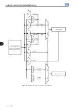
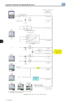
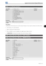
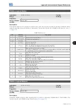
These parameters define the origin source for the speed reference in the Local situation and Remote situation.
Some comments on the options of this parameter:
AIx:
it refers to the analog input signal according to
Section 12.1 ANALOG INPUTS on page 12-1
HMI:
the reference value set by the keys
and
contained in parameter P0121.
E.P.:
electronic potentiometer; refer to
Section 12.5 DIGITAL INPUTS on page 12-14
.
Multispeed:
refer to
Section 12.5 DIGITAL INPUTS on page 12-14
.
When P0203 = 1, the value set in P0221 and P0222 becomes the PID Setpoint and no longer the speed
reference. The PID Setpoint is shown in P0040 and saved in P0525 when the source is the HMI keys.
AIx > 0:
the negative values of the AIx reference are zeroed.
CO/DN/PB/Eth:
CANopen, DeviceNet, Profibus DP or Ethernet Interface.
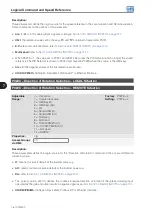
P0223 – Direction of Rotation Selection – LOCAL Situation
P0226 – Direction of Rotation Selection – REMOTE Situation
Adjustable
Range:
0 = Clockwise
1 = Counterclockwise
2 = HMI Key (H)
3 = HMI Keys (AH)
4 = DIx
5 = Serial/USB (H)
6 = Serial/USB (AH)
7 = Not Used
8 = Not Used
9 = CO/DN/PB/Eth (H)
10 = CO/DN/PB/Eth (AH)
11 = Not Used
12 = SoftPLC
Factory
Setting:
P0223 = 2
P0226 = 4
Properties:
cfg
Access Groups
via HMI:
I/O
Description:
These parameters define the origin source for the “Direction of Rotation" command in the Local and Remote
situation, where:
H:
means clockwise default at the inverter power-up.
AH:
means counterclockwise default at the inverter power-up.
DIx:
refer to
Section 12.5 DIGITAL INPUTS on page 12-14
The polarity option AI3 (11) defines the counterclockwise direction of rotation if the referred analog input
operated by the gain and offset results in negative signal as per
Section 12.1 ANALOG INPUTS on page 12-1
.
CO/DN/PB/Eth
: CANopen, DeviceNet, Profibus DP or Ethernet Interface.
Summary of Contents for CFW500 V1.8X
Page 2: ......
Page 4: ......
Page 8: ...Contents...
Page 34: ...General Information 2 4 CFW500...
Page 38: ...About the CFW500 3 4 CFW500 3...
Page 42: ...HMI and Basic Programming 4 4 CFW500 4...
Page 52: ...Programming Basic Instructions 5 10 CFW500 5...
Page 56: ...Identification of the Inverter Model and Accessories 6 4 CFW500 6...
Page 76: ...Available Motor Control Types 8 4 CFW500 8...
Page 84: ...V f Scalar Control 9 8 CFW500 9...
Page 170: ...Communication 17 8 CFW500 17...

