V/f Scalar Control
9-6 | CFW500
9
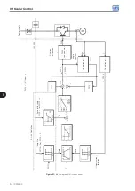
Voltage
applied on
the motor
Output
active
current
Speed reference
P0139
I x R
P0136
I x R
Automatic
P0137
P0007
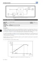
Figure 9.4:
Block diagram of the automatic torque boost
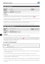
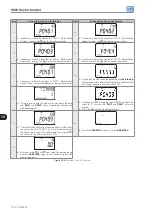
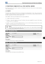
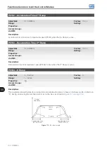
P0138 – Slip Compensation
Adjustable
Range:
-10.0 to 10.0 %
Factory
Setting:
0.0 %
Properties:
V/f
Access Groups
via HMI:
MOTOR
Description:
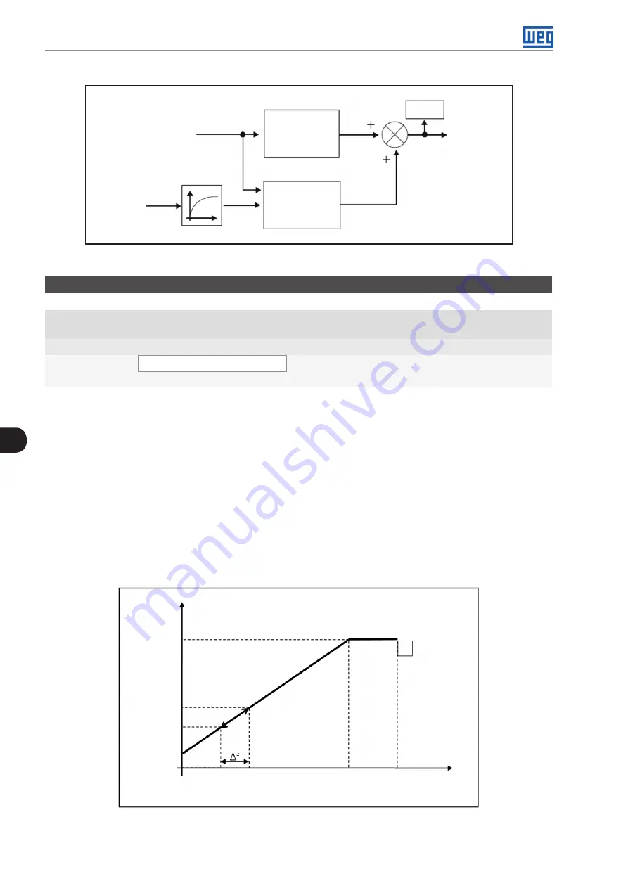
Parameter P0138 is used in the motor slip compensation function, when set for positive values. In this case, it
compensates the speed drop due to application of the load on the shaft and, consequently, the slip. In this way,
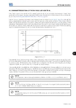
it increments the output frequency (Δf) considering the increase of the motor active current as shown in
this compensation is represented in the variable
f
Slip
.
The setting in P0138 allows regulating with good accuracy the slip compensation by moving the operation point
on the V/f curve, as shown in
. Once P0138 is set, the inverter is able to keep the speed
constant even with load variations.
Negative values are used in special applications where you wish to reduce the output speed considering the
increase of the motor current.
E.g.: load distribution in motors driven in parallel.
P0134
P0145
P0146
P0147
P
4
P0142
P0143
P0144
P0136
Output
frequency (Hz)
Output
voltage (%)
Figure 9.5:
Slip compensation in an operation point of the standar V/f curve
Summary of Contents for CFW500 V1.8X
Page 2: ......
Page 4: ......
Page 8: ...Contents...
Page 34: ...General Information 2 4 CFW500...
Page 38: ...About the CFW500 3 4 CFW500 3...
Page 42: ...HMI and Basic Programming 4 4 CFW500 4...
Page 52: ...Programming Basic Instructions 5 10 CFW500 5...
Page 56: ...Identification of the Inverter Model and Accessories 6 4 CFW500 6...
Page 76: ...Available Motor Control Types 8 4 CFW500 8...
Page 84: ...V f Scalar Control 9 8 CFW500 9...
Page 170: ...Communication 17 8 CFW500 17...

