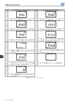
VVW Vector Control
10-8 | CFW500
10
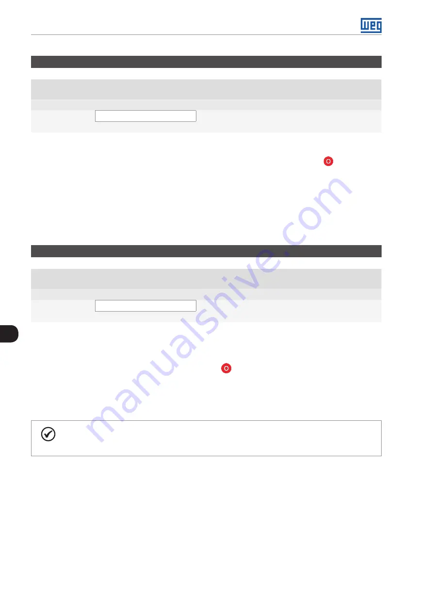
P0408 – Self-Tuning
Adjustable
Range:
0 = No
1 = Yes
Factory
Setting:
0
Properties:
cfg, V VW
Access Groups
via HMI:
STARTUP
Description:
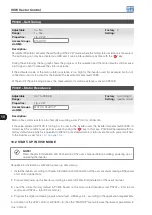
Parameter P0408 in 1 activates the self-tuning of the V VW mode, where the motor stator resistance is measured.
The self-tuning can only be activated via HMI, and it can be interrupted at any time with the "
" key.
During the self-tuning, the bar graph shows the progress of the operation and the motor remains still, because
a DC signal is sent to measure the stator resistance.
If the estimated value of the motor stator resistance is too high for the inverter used (for example: motor not
connected or motor too small for the inverter) the inverter indicates fault F0033.
At the end of the self-tuning process, the measured motor stator resistance is saved in P0409.
P0409 – Stator Resistance
Adjustable
Range:
0.01 to 99.99 Ω
Factory
Setting:
According to
inverter model
Properties:
cfg, V VW
Access Groups
via HMI:
MOTOR, STARTUP
Description:
Motor phase stator resistance in ohms (Ω), assuming a star (Y) motor connection.
If the value adjusted in P0409 is too high or too low for the inverter used, the inverter indicates fault F0033. In
order to exit this condition, just perform a reset by using the “
” key. In this case, P0409 will be loaded with the
factory default value which is equivalent to WEG IV pole standard motor stator resistance with power matched
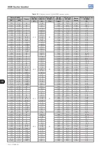
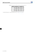
to the inverter, as per
.
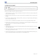
10.2 START-UP IN VVW MODE
NOTE!
Read chapter 3 Installation and Connection of the user’s manual before installing, powering up or
operating the inverter.
Sequence for installation, verification, power up and start-up.
1. Install the inverter according to chapter 3 Installation and Connection of the user’s manual, making all the power
and control connections.
2. Prepare and power up the inverter according to section 3.2 Electrical Installation of the user’s manual.
3. Load the correct factory default in P0204 based on the motor rated frequency (set P0204 = 5 for 60 Hz
motors and P0204 = 6 for 50 Hz motors).
4. Program the digital and analog inputs and outputs, HMI keys, etc., according to the application requirements.
5. Activation of the V VW control: set P0202 = 5; then the “STARTUP” menu browses the relevant parameters to
Summary of Contents for CFW500 V1.8X
Page 2: ......
Page 4: ......
Page 8: ...Contents...
Page 34: ...General Information 2 4 CFW500...
Page 38: ...About the CFW500 3 4 CFW500 3...
Page 42: ...HMI and Basic Programming 4 4 CFW500 4...
Page 52: ...Programming Basic Instructions 5 10 CFW500 5...
Page 56: ...Identification of the Inverter Model and Accessories 6 4 CFW500 6...
Page 76: ...Available Motor Control Types 8 4 CFW500 8...
Page 84: ...V f Scalar Control 9 8 CFW500 9...
Page 170: ...Communication 17 8 CFW500 17...

