Digital and Analog Inputs and Outputs
CFW500 | 12-13
12
P0257 – Frequency Output Function FO
Adjustable
Range:
0 = Speed Reference
1 = Not Used
2 = Real Speed
3 = Not Used
4 = Not Used
5 = Output Current
6 = Process Variable
7 = Active Current
8 = Not Used
9 = PID Setpoint
10 = Not Used
11 = Motor Torque
12 = SoftPLC
13 = Not Used
14 = Not Used
15 = Disable FO
16 = Motor Ixt
17 = Not Used
18 = Value of P0696
19 = Value of P0697
20 = Value of P0698
21 = Function 1 of Application
22 = Function 2 of Application
23 = Function 3 of Application
24 = Function 4 of Application
25 = Function 5 of Application
26 = Function 6 of Application
27 = Function 7 of Application
28 = Function 8 of Application
Factory
Setting:
15
Properties:
Access Groups
via HMI:
I/O
Description:
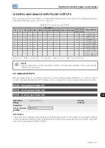
This parameter sets the frequency output function similarly to the setting of the analog outputs, like function and
scale present in
.
The transistor digital output DO2 function is defined by P0276 when the frequency output function is inactive,
that is, P0257 = 15. However, any other option of P0257 and the digital output DO2 becomes the frequency
output ignoring the digital output function set in P0276.
Table 12.5:
Full scale of frequency output
Function
Description
Full Scale
0
Speed reference in the ramp input (P0001).
P0134
2
Real speed in the inverter output (P0002).
P0134
5
Total output current in RMS.
2xP0295
6
PID process variable.
P0528
7
Active current.
2xP0295
9
PID Setpoint.
P0528
11
Motor torque in relation to rated torque.
200.0 %
12
SoftPLC scale for frequency output.
32767
15
Inactive frequency output - DO2 is digital output.
-
16
Motor overload Ixt (P0037).
100 %
18
Value of P0696 for analog output AOx.
32767
19
Value of P0697 for analog output AOx.
32767
20
Value of P0698 for analog output AOx.
32767
21 to 28
Defined value SoftPLC application on WLP.
32767
Summary of Contents for CFW500 V1.8X
Page 2: ......
Page 4: ......
Page 8: ...Contents...
Page 34: ...General Information 2 4 CFW500...
Page 38: ...About the CFW500 3 4 CFW500 3...
Page 42: ...HMI and Basic Programming 4 4 CFW500 4...
Page 52: ...Programming Basic Instructions 5 10 CFW500 5...
Page 56: ...Identification of the Inverter Model and Accessories 6 4 CFW500 6...
Page 76: ...Available Motor Control Types 8 4 CFW500 8...
Page 84: ...V f Scalar Control 9 8 CFW500 9...
Page 170: ...Communication 17 8 CFW500 17...


