Digital and Analog Inputs and Outputs
CFW500 | 12-25
12
Table 12.8:
Digital output functions
Value
Function
Description
0
Not Used.
Digital output inactive.
1
F* > Fx.
Active when the speed reference F* (P0001) is greater than Fx (P0288).
2
F > Fx.
Active when output frequency F (P0002) is greater than Fx (P0288).
3
F < Fx.
Active when output frequency F (P0002) is smaller than Fx (P0288).
4
F = F*.
Active if the output frequency F (P0002) is equal to reference F* (P0001) (ramp end).
5
Not Used.
Digital output inactive.
6
Is > Ix.
Active if the output current Is (P0003) > Ix (P0290).
7
Is < Ix.
Active if the output current Is (P0003) < Ix (P0290).
8
Torque > Tx.
Active if the motor torque T (P0009) > Tx (P0293).
9
Torque < Tx.
Active if the motor torque T (P0009) < Tx (P0293).
10
Remote.
Active if the command is the Remote condition (REM).
11
Run.
Active if the motor is running (active output PWM pulses) RUN status.
12
Ready.
Active if the inverter is ready for enabling.
13
No Fault.
Active if the inverter has no fault.
14
No F0070.
Active if the inverter has no overcurrent fault (F0070).
15
Not Used.
Digital output inactive.
16
No F0021/22.
Active if the inverter has no overvoltage or undervoltage fault (F0022 or F0021).
17
Not Used.
Digital output inactive.
18
No F0072.
Active if the inverter has no motor overload fault (F0072).
19
4-20 mA OK.
Active if AIx is set for 4 to 20 mA (P0233 and/or P0238 and/or P0243 equal to 1 or 3) and AIx < 2 mA.
20
Value of P0695.
Status of the bits 0 to 4 of P0695 activate digital outputs DO1 to DO5, respectively.
21
Clockwise.
Active if the inverter direction of rotation is clockwise.
22
Proc. V. > VPx.
Active if process variable (P0040) > VPx (P0533).
23
Proc. V. < VPx.
Active if process variable (P0040) < VPx (P0533).
24
Ride-Through.
Active if the inverter is executing the Ride-Through function.
25
Pre-Charge OK.
Active if the pre-charge relay of the DC link capacitors was already activated.
26
With Fault.
Active if the inverter has a fault.
27
Not Used.
Digital output inactive.
28
SoftPLC.
Activates DOx output according to the SoftPLC memory area. Read the SoftPLC user’s manual.
29 ... 34 Not Used.
Digital output inactive.
35
No Alarm.
Active when the inverter has no alarm.
36
No Fault and Alarm.
Active when the inverter has no alarm and no fault.
37
Function 1 Application.
38
Function 2 Application.
39
Function 3 Application.
40
Function 4 Application.
41
Function 5 Application.
42
Function 6 Application.
43
Function 7 Application.
44
Function 8 Application.
P0287 – Fx Hysteresis
P0288 – Fx Speed
Adjustable
Range:
0.0 to 500.0 Hz
Factory
Setting:
P0287 = 0.5 Hz
P0288 = 3.0 Hz
Properties:
Access Groups
via HMI:
I/O
Description:
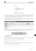
These parameters set the hysteresis and actuation level on the Fx output frequency signal and on the F* ramp
input of the relay digital outputs. In this way, the relay commutation levels are "P0288 + P0287" and "P0288 -
P0287".
Summary of Contents for CFW500 V1.8X
Page 2: ......
Page 4: ......
Page 8: ...Contents...
Page 34: ...General Information 2 4 CFW500...
Page 38: ...About the CFW500 3 4 CFW500 3...
Page 42: ...HMI and Basic Programming 4 4 CFW500 4...
Page 52: ...Programming Basic Instructions 5 10 CFW500 5...
Page 56: ...Identification of the Inverter Model and Accessories 6 4 CFW500 6...
Page 76: ...Available Motor Control Types 8 4 CFW500 8...
Page 84: ...V f Scalar Control 9 8 CFW500 9...
Page 170: ...Communication 17 8 CFW500 17...


