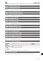
Communication
CFW500 | 17-1
17
17 COMMUNICATION
In order to exchange information via communication network, the CFW500 features several standardized
communication protocols, such as Modbus, CANopen and DeviceNet.
For further details referring to the inverter configuration to operate in those protocols, refer to the CFW500
user’s manual for communication with the desired network. Below are listed the parameters related to the
communication.
17.1 SERIAL USB, RS-232 AND RS-485 INTERFACE
Depending on the plug-in module installed, the CFW500 features up to two simultaneous serial interfaces;
however, only one of them can be source for commands or references; the other is inactive or remote HMI
according to the selection of P0312.
One of those interfaces, identified as Serial (1), is the CFW500 standard interface and is present in all the plug-in
modules through the terminals of the RS-485 standard port. On the other hand, Serial (2) interface is only present
in the CFW500-CUSB, CFW500-CRS232 and CFW500-CRS485 plug-in modules, as per the figures below:
Figure 17.1:
Plug-in module CFW500-IOS
Figure 17.2:
Plug-in module CFW500-CRS232
Figure 17.3:
Plug-in module CFW500-CUSB
Figure 17.4:
Plug-in module CFW500-CRS485
NOTE!
The CFW500-IOS plug-in module has only Serial (1) interface through RS-485 port at terminals 12(A-)
and 14(B+), see
Summary of Contents for CFW500 V1.8X
Page 2: ......
Page 4: ......
Page 8: ...Contents...
Page 34: ...General Information 2 4 CFW500...
Page 38: ...About the CFW500 3 4 CFW500 3...
Page 42: ...HMI and Basic Programming 4 4 CFW500 4...
Page 52: ...Programming Basic Instructions 5 10 CFW500 5...
Page 56: ...Identification of the Inverter Model and Accessories 6 4 CFW500 6...
Page 76: ...Available Motor Control Types 8 4 CFW500 8...
Page 84: ...V f Scalar Control 9 8 CFW500 9...
Page 170: ...Communication 17 8 CFW500 17...

