HMI and Basic Programming
CFW500 | 4-1
4
4 HMI AND BASIC PROGRAMMING
4.1 USE OF THE HMI TO OPERATE THE INVERTER
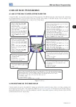
Through the HMI, it is possible to view and set all the parameters. The HMI features two operating modes: monitoring
and parameterization. The functions of the keys and the active fields on the HMI display vary according to the
operating mode. The setting mode is composed of three levels.
Press this key to accelerate the motor up to the speed set in P0122 within the time determined by
the acceleration ramp. The motor speed is kept while the key is pressed. When the key is released,
the motor decelerates within the time determined by the deceleration ramp, until it stops.
This function is active when all the conditions below are met:
1. Run/Stop = Stop.
2. General Enable = Active.
3. P0225 = 1 in LOC and/or P0228 = 1 in REM.
Press this key to commute between
LOCAL and REMOTE mode. Active
when:
P0220 = 2 or 3.
Press this key to define the motor
rotation direction.
Active when:
P0223 = 2 or 3 in LOC and/or
P0226 = 2 or 3 in REM.
- When in the setting mode,
level
1
: press this key to return to the
monitoring mode.
- When in the setting mode,
level 2
:
press this key to return to
level 1
of
the setting mode.
- When in the setting mode,
level 3
:
press this key to cancel the new
value (new value is not saved) and
return to
level 2
of the setting
mode.
- When in the monitoring mode: press
this key to increase the speed.
- When in the setting mode,
level 1
:
press this key to go to the previous
group.
- When in the setting mode,
level
2
: press this key to go to the next
parameter.
- When in the setting mode,
level
3
: press this key to increase the
content of the parameter.
- When in the monitoring mode: press this key to
enter the setting mode.
- When in the setting mode,
level 1
: press this key
to select the desired parameter group – it shows
the parameter group selected.
- When in the setting mode,
level 2
: press this key
to show the parameter – it shows the content of
the parameter for the modification.
- When in the setting mode,
level 3
: press this
key to save the new content of the parameter – it
returns to
level 2
of the setting mode.
- When in the monitoring mode: press this key to
decrease the speed.
- When in the setting mode,
level 1
: press this key
to go to the next group.
- When in the setting mode,
level 2
: press this key
to show the previous parameter.
- When in the setting mode,
level 3
: press this key
to decrease the content of the parameter.
Press this key to accelerate the motor within the
time determined by the acceleration ramp. Active
when:
P0224 = 0 in LOC or
P0227 = 0 in REM.
Press this key to decelerate the motor within the
time determined by the deceleration ramp.
Active when:
P0224 = 0 in LOC or
P0227 = 0 in REM.
Figure 4.1:
HMI keys
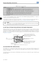
4.2 INDICATIONS ON THE HMI DISPLAY
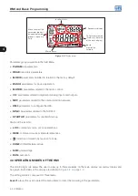
The information shown on the HMI LCD display are divided into six fields: menu, status, secondary display, unit,
main display and bar graph. Those fields are defined in
. The main and secondary displays
allow alternating the focus to scroll the parameter number or parameter value according to levels 2 and 3 of the
parameterization mode, respectively.
Summary of Contents for CFW500 V1.8X
Page 2: ......
Page 4: ......
Page 8: ...Contents...
Page 34: ...General Information 2 4 CFW500...
Page 38: ...About the CFW500 3 4 CFW500 3...
Page 42: ...HMI and Basic Programming 4 4 CFW500 4...
Page 52: ...Programming Basic Instructions 5 10 CFW500 5...
Page 56: ...Identification of the Inverter Model and Accessories 6 4 CFW500 6...
Page 76: ...Available Motor Control Types 8 4 CFW500 8...
Page 84: ...V f Scalar Control 9 8 CFW500 9...
Page 170: ...Communication 17 8 CFW500 17...

