background image

144 | CFW501

Appendix B / Anexo B

A

pp
en

d

ix

 B

A

ne

xo

 B

12

8.

5 [

5.1

]

30

5.

7 [

12

]

30

6.

6 [

12

.1

]

R4

 [0

.2]

A

B

29

0 [

11

.4

]

9.

8 [

0.

4]

99.

6 [

3.

9]

125 [4.9]

166.4 [6.6]

86.

7 [3

.4

]

180 [7.1]

84 [3.3]

42

.6

 [1.

7]

125 [4.9]

5.9 [0.2]

8 [0.3]

26

.8

 [1

.1

]

26

.8

 [1

.1

]

7.

2 [

0.

3]

7.

2 [

0.

3]

B

10.1 [0.4]

A

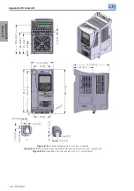
Figure B.7:

 Inverter dimensions in mm [in] – frame D

 Figura B.7:

 Dimensiones del convertidor de frecuencia en mm [in] – tamaño D

Figura B.7:

  Dimensões do inversor em mm [in] – mecânica D

Summary of Contents for CFW501

Page 1: ...nverter Convertidor de Frecuencia Inversor de Frequ ncia CFW501 Motors Automation Energy Transmission Distribution Coatings User s Manual Manual del Usuario Manual do Usu rio Language English Spanish...

Page 2: ...User s Manual Series CFW501 Language English Document 10001991016 04 Models Frame A D Date 06 2015...

Page 3: ...of the power supply The CFW501 inverters have the factory default parameters set for line frequency of 60 Hz In case the power supply frequency is different from the 60 Hz it is necessary to set P0204...

Page 4: ...ower and Grounding Wiring Circuit Breakers and Fuses 11 3 2 3 Power Connections 12 3 2 3 1 Input Connections 13 3 2 3 2 IT Networks 13 3 2 3 3 Dynamic Braking 14 3 2 3 4 Output Connections 15 3 2 4 Gr...

Page 5: ...AL ASSISTANCE 34 6 4 PREVENTIVE MAINTENANCE 34 6 5 CLEANING INSTRUCTIONS 35 7 OPTIONAL KITS AND ACCESSORIES 36 7 1 OPTIONAL KITS 36 7 1 1 Protection Rate Nema1 36 7 2 ACCESSORIES 36 8 TECHNICAL SPECIF...

Page 6: ...r damages to the equipment 1 1 SAFETY WARNINGS IN THIS MANUAL DANGER The procedures recommended in this warning aim at protecting the user against death serious injuries and considerable material dama...

Page 7: ...of the inverter to the protection grounding NOTES Frequency inverters may interfere in other electronic equipment Observe the recommendations of chapter 3 Installation and Connection in order to mini...

Page 8: ...can be requested at your local WEG dealer NOTE It is not the intention of this manual to present all the possibilities for the application of the CFW501 as well as WEG cannot take any liability for th...

Page 9: ...insulated gate bipolar transistors and current feedback Power supply R L1 L S L2 N T L3 Bus connection CC Connection for brake resistor Preload Software WLP SUPERDRIVE MODBUS Capacitor bank link CC B...

Page 10: ...RDRIVE MODBUS Capacitor bank link CC Braking IGBT available in the inverters CFW500 DB HMI CPU 32 bits RISC EEPROM memory User s Plug in card Interfaces RS 232 RS 485 or USB Analog output AO1 Power su...

Page 11: ...ternal filter In order to comply with IEC 61800 3 refer to table B 3 and check the operation conditions The available options for each model are in table 2 2 Table 2 2 Available options for each field...

Page 12: ...de of the inverter Stock item Manufacturing date Serial number Side Label of the CFW501 Manufacturing date Production order Rated input data voltage current and frequency Rated input data voltage curr...

Page 13: ...tion temperature between 25 C and 60 C 77 F and 140 F with a cover to prevent dust accumulation inside it ATTENTION When the inverter is stored for a long period it becomes necessary to perform the ca...

Page 14: ...above 2000 m 6 600 ft Pollution degree 2 according to EN 50178 and UL 508C with non conductive pollution Condensation must not originate conduction through the accumulated residues 3 1 2 Positioning a...

Page 15: ...FW501 on the mounting surface 3 1 2 3 DIN Rail Mounting The inverter CFW501 can also be mounted directly on 35 mm rail as per DIN EN 50 022 For this mounting you must first position the lock down and...

Page 16: ...power terminals and grounding points must be checked in figure B 3 3 2 2 Power and Grounding Wiring Circuit Breakers and Fuses ATTENTION Use proper cable lugs for the power and grounding connection c...

Page 17: ...T Input power supply PE W V U R BR S T U Ud Ud V W PE PE The power terminals Ud BR and Ud are not available in models of frame A a Frame A B and C Shield PE Disconnecting switch Fuses R S T Input pow...

Page 18: ...mum impedance of the input power supply permitted is 1 of the voltage drop It is not permitted the use of inducer on the DC link Power supply capacity The CFW501 is suitable for use in a circuit capab...

Page 19: ...wer supply Thermostat Brake resistor Relay Command power supply Contactor BR Ud R S T Figure 3 2 Installation of brake resistor The effective braking current can be calculated as follows Ieffective Im...

Page 20: ...level on the DC bus for activation of the dynamic braking is defined by the parameter P0153 level of the dynamic braking Refer to the CFW501 programming manual 3 2 3 4 Output Connections ATTENTION Th...

Page 21: ...ol cable shield Figure 3 3 Details of the connection of the power supply and the motor cable shield to the accessory CFW500 KPCSA 3 2 4 Grounding Connections DANGER The inverter must be connected to a...

Page 22: ...he package of the product or in the CD manual of the product The typical functions and connections for the CFW500 CRS485 plug in module are shown in figure 3 4 For further details about the specificat...

Page 23: ...Terminal B2 24 GND Reference 0 V The digital input 2 DI2 can also be used as input in frequency FI For further details refer to the programming manual of the CFW501 For further information refer to th...

Page 24: ...erse reference Current S2 1 ON 0 20 mA P0238 0 direct reference or 2 inverse reference 4 20 m A P0238 1 direct reference or 3 inverse reference AO1 Voltage S1 2 ON 0 10 V P0253 0 direct reference or 3...

Page 25: ...he control circuitry To eliminate this effect RC suppressors with AC power supply or freewheel diodes with DC power supply must be connected in parallel to the coils of these devices 5 When using the...

Page 26: ...grounding switch of the capacitors of the internal RFI filter in the position Check the location of the grounding switch in figure A 2 2 Shielded output cables motor cables with shield connected at b...

Page 27: ...V m 80 AM 1 kHz Definition of Standard IEC EM 61800 3 Adjustable Speed Electrical Power Drives Systems Environments First Environment Environments that include domestic installations as well as establ...

Page 28: ...ss this key to cancel the new value new value is not saved and return to level 2 of the setting mode When in the monitoring mode press this key to increase the speed When in the setting mode level 1 p...

Page 29: ...meters READ reading parameters only MODIF parameters modified in relation to the default only BASIC parameters for basic application MOTOR parameters related to the control of the motor I O parameters...

Page 30: ...mmute to the setting mode Monitoring Setting Level 1 Setting Level 2 Setting Level 3 BACK ESC BACK ESC BACK ESC ENTER MENU ENTER MENU ENTER MENU Setting Mode Level 1 This is the first level of the set...

Page 31: ...splay until the fault is reset NOTE When the inverter is in the alarm state the main display indicates the number of the alarm in the format Axxxx The browsing is allowed after the activation of any k...

Page 32: ...ot be uncoupled be sure that the turning in any direction clockwise or counterclockwise will not cause damages to the machine or risk of accidents 5 Close the covers of the inverters or drive 6 Measur...

Page 33: ...til selecting the STARTUP group If necessary modify the content of P0400 Motor Rated Voltage Press the key for the next parameter 3 8 When the STARTUP group is selected Press the key ENTER MENU If nec...

Page 34: ...or press the key for the next parameter To exit the STARTUP menu just press BACK ESC 12 14 If necessary modify the content of P0407 Motor Rated Power Factor or press the key for the next parameter Thr...

Page 35: ...RTUP group If necessary modify the content of P0398 Motor Service Factor Press the key for the next parameter 3 8 When the STARTUP group is selected press the key ENTER MENU If necessary modify the co...

Page 36: ...ontent of P0404 Motor rated power or press the key for the next parameter The result of Self Adjustment is the value in ohms of the motor stator resistance shown in P0409 This is the last parameter of...

Page 37: ...ify the content of P0134 Maximum Speed Press the key for the next parameter 3 8 When the BASIC group is selected press the key ENTER MENU If necessary modify the content of P0135 Maximum Output Curren...

Page 38: ...ctions 2 Check all the internal connections of the inverter Defective speed reference potentiometer 1 Replace the potentiometer Oscillation of the external analog reference 1 Identify the cause of the...

Page 39: ...directly on the components or connectors If necessary first touch the grounded metallic frame or use proper grounding strap Do not execute any applied potential test on the inverter If necessary conta...

Page 40: ...he CFW501 can be easily replaced as shown in figure 6 1 6 5 CLEANING INSTRUCTIONS When it is necessary to clean the inverter follow the instructions below Ventilation system Disconnect the power suppl...

Page 41: ...g of the inverter 7 2 ACCESSORIES The accessories are hardware resources that can be added in the application Thus all models can receive all the options presented The accessories are incorporated to...

Page 42: ...KN1A Nema1 kit for frame size A standard for option N1 12254901 CFW501 KN1B Nema1 kit for frame size B standard for option N1 12254902 CFW501 KN1C Nema1 Kit for frame size C standard for option N1 132...

Page 43: ...d inputs Levels 0 to 10 V or 0 a 20 mA or 4 to 20 mA Linearity error 0 25 Impedance 100 k for voltage input 500 for current input Programmable functions Maximum voltage permitted in the input 30 Vdc D...

Page 44: ...Overload in the power module IGBTs External alarm fault Setting error HUMAN MACHINE INTERFACE HMI STANDARD HMI 9 keys Start Stop Up arrow Down arrow Direction of Rotation Jog Local Remote BACK ESC and...

Page 45: ...including specific test methods EN 55011 Limits and methods of measurement of radio disturbance characteristics of industrial scientific and medical ISM radio frequency equipment CISPR 11 Industrial s...

Page 46: ...Manual del Usuario Serie CFW501 Idioma Espa ol Documento 10001991016 04 Modelos Tam A D Fecha 06 2015...

Page 47: ...ntacion Los convertidores CFW501 presentan los par metros de f brica ajustados para la frecuencia de red 60 Hz En caso que la frecuencia de la red de alimentacion sea diferente de 60 Hz es necesario p...

Page 48: ...Aterramiento Disyuntores y Fusibles 56 3 2 3 Conexiones de Potencia 57 3 2 3 1 Conexiones de Entrada 58 3 2 3 2 Redes IT 58 3 2 3 3 Frenado Reost tico 59 3 2 3 4 Conexiones de Salida 60 3 2 4 Conexion...

Page 49: ...ISTENCIA T CNICA 78 6 4 MANTENIMIENTO PREVENTIVO 78 6 5 INSTRUCCIONES DE LIMPIEZA 79 7 OPCIONALES Y ACCESORIOS 80 7 1 OPCIONALES 80 7 1 1 Grado de Protecci n Nema1 80 7 2 ACCESORIOS 80 8 ESPECIFICACIO...

Page 50: ...riesgo de muerte y o da os en el equipamiento 1 1 AVISOS DE SEGURIDAD EN EL MANUAL PELIGRO Los procedimentos recomendados en este aviso tienen como objetivo proteger al usuario contra muerte heridas...

Page 51: ...a tierra de protecci n PE NOTAS Los inversores de frecuencia pueden interferir en otros equipamientos electr nicos Siga los cuidados recomendados en el cap tulo 3 Instalaci n Y Conexi n para minimiza...

Page 52: ...hivos disponibilizados en el CD puede solicitarse por medio de su representante local WEG NOTA La intenci n de este manual no es agotar todas las posibilidades de aplicaci n del CFW501 ni WEG puede as...

Page 53: ...tores IGBT y realimentaci n de corriente Red de alimentaci n R Li L S L2 N T L3 Conexi n enlace CC Conexi n para resistor de frenado Precarga Software WLP SUPERDRIVE MODBUS Banco capacitores Iink CC I...

Page 54: ...s CFW500 DB CPU 32 bits RISC EEPROM memoria Cart o Plug in del usuario Interfaces RS 232 RS 485 o USB Salida anal gica AO1 Fuente 24 V Fuente 10 V Salida digital DO1 RL1 y DO3 RL2 Salida digital DO2 T...

Page 55: ...iltro interno Para atender la norma IEC 61800 3 consulte la tabla B 3 para verificar las condiciones de operaci n Las opciones disponibles para cada modelo aparecen en la tabla 2 2 Tabla 2 2 Opciones...

Page 56: ...em de stock Fecha de fabricaci n N mero de serie Etiqueta Lateral del CFW501 Fecha de fabricaci n Orden de producci n Datos nominales de entrada tensi n corriente y frecuencia Datos nominales de salid...

Page 57: ...lmac nelo en un lugar limpio y seco temperatura entre 25 C y 60 C con una cobertura para evitar la entrada de polvo en el interior del convertidor ATENCI N Cuando el convertidor es almacenado por larg...

Page 58: ...por encima del nivel del mar aplicar 1 1 de reducci n de la tensi n m xima 240 Vca para los modelos 200 240 Vca y 480 Vca para los modelos 380 480 Vca para cada 100 metros por encima de 2000 metros Gr...

Page 59: ...re de ventilaci n nominal para cada mec nica M todo de Refrigeraci n ventilador interno con flujo de aire de abajo para arriba Tabla 3 1 Flujo de aire del ventilador interno Mec nica CFM I s m3 min A...

Page 60: ...os y configuraciones dependiendo del modelo del convertidor seg n la figura B 3 La localizaci n de las conexiones de potencia aterramiento y control puede ser visualizada en la figura A 3 Descripci n...

Page 61: ...al DR Cuando utilizado en la alimentaci n del convertidor deber presentar corriente de actuaci n de 300 mA Dependiendo de las condiciones de instalaci n como longitud y tipo del cable del motor accion...

Page 62: ...s R S T Red PE W y U R BR S T U Ud Ud y W PE PE Los bornes de potencia Ud BR y Ud no est n disponibles en los modelos de la Mec nica A a Tama os A B y C Blindaje PE Seccionadora Fusibles R S T Red PE...

Page 63: ...en la salida U V W La impedancia m xima de red permitida es de 1 de ca da de tensi n No est permitida la utilizaci n de inductor en el enlace CC Capacidad de la red de alimentaci n El CFW501 es propio...

Page 64: ...rmico Alimentaci n de comando Contactor BR Ud R S T Figura 3 2 Conexi n del resistor de frenado La corriente eficaz de frenado puede ser calculada a trav s de Ieficaz Imax tbr min 5 Siendo tbr corresp...

Page 65: ...tico es definido por el par metro P0153 nivel del frenado reost tico Consulte el manual de programaci n del CFW501 3 2 3 4 Conexiones de Salida ATENCI N El convertidor posee protecci n electr nica de...

Page 66: ...l blindaje de los cables de control Figura 3 3 Detalle de la conexi n del blindaje de los cables de la red de alimentaci n y del motor con accesorio CFW500 KPCSA 3 2 4 Conexiones de Aterramiento PELIG...

Page 67: ...cnicas AI1 AO1 GND 10 V DO2 TR R rpm GND RS485 B RS485 B2 24 V 24 V DO1 RL NO DO3 RL NO DO1 RL C DO3 RL C DO1 RL NC DO3 RL NC NC DI1 DI2 DI3 DI4 RS485 A RS485 A2 5 k GND AI2 Figura 3 4 a Se ales del c...

Page 68: ...al en tensi n 0 10 V y con resistores de terminaci n del RS485 apagados NOTA Para utilizar las entradas y o salidas anal gicas con se al en corriente se debe ajustar las llaves S1 y S2 y los par metro...

Page 69: ...el mismo debe ser hecho de forma perpendicular entre los mismos manteniendo el alejamiento m nimo de 5 cm en este punto Conectar el blindaje de acuerdo con la figura abajo No Aterrar Aislar con Cinta...

Page 70: ...profesionales Por eso no se aplican los l mites de emisiones de corrientes harm nicas definidas por las normas EN 61000 3 2 y EN 61000 3 2 A 14 3 3 1 Instalaci n Conforme 1 Inversores con opci n filt...

Page 71: ...gn tico de Radiofrecuencia lEC 61000 4 3 80 a 1000 MHz 10 V m 80 AM 1 kHz Definiciones de la Norma IEC EM 61800 3 Adjustable Speed Electrical Power Drives Systems Ambientes Primer Ambiente First Envir...

Page 72: ...el nuevo valor y retornar al nivel 2 del modo parametrizaci n Cuando est en el modo monitoraci n presione la tecla para aumentar la velocidad Cuando est en el modo parametrizaci n nivel 1 presione est...

Page 73: ...D solamente los par metros de lectura MODIF solamente par metros alterados en relaci n al est ndar de f brica BASIC par metros para aplicaci n b sica MOTOR par metros relacionados al control del motor...

Page 74: ...a para el modo parametrizaci n Monitoreo Parametrizaci n Nivel 1 Parametrizaci n Nivel 2 Parametrizaci n Nivel 3 BACK ESC BACK ESC BACK ESC ENTER MENU ENTER MENU ENTER MENU Modo Parametrizaci n NiveI...

Page 75: ...la falta sea reseteada NOTA Cuando el convertidor est en estado de alarma el display principal indica el n mero de la alarma en formato Axxxx La navegaci n es permitida luego del accionamiento de cua...

Page 76: ...el motor no puede ser desacoplado tenga la certeza de que el giro en qualquier direcci n horario o antihorario no causar da os a la m quina o risego de accidentes 5 Cierre las tapas del convertidor o...

Page 77: ...seleccionar el grupo STARTUP Si es necesario altere el contenido de P0400 Tensi n nominal del motor o presione la tecla para el pr ximo par metro 3 8 Cuando seleccionado el grupo STARTUP presione la t...

Page 78: ...cla para el pr ximo par metro Para salir del men STARTUP basta presionar BACK ESC 12 14 Si es necesario altere el contenido de P0407 Factor de Potencia nominal del motor o presione la tecla para el pr...

Page 79: ...s necessario altere el contenido de P0398 Factor Servicio Motor la tecla para el pr ximo par metro 3 8 Cuando seleccionado el grupo STARTUP presione la tecla ENTER MENU Si es necesario altere el conte...

Page 80: ...04 Potencia nominal del motor o presione la tecla para el pr ximo par metro El resultado del Autoajuste es el valor en ohms de la resistencia estat rica mostrada en P0409 Este es el ltimo par metro de...

Page 81: ...P0134 Velocidad M xima Presione la tecla para el pr ximo par metro 3 8 Cuando seleccionado el grupo BASIC presione la tecla ENTER MENU Si es necesario altere el contenido de P0135 Corriente M xima Sal...

Page 82: ...l apriete de todas las conexiones internas del convertidor Potenci metro de referencia con defecto 1 Sustituir el potenci metro Variaci n de la referencia anal gica externa 1 Identificar el motivo de...

Page 83: ...aso que fuera necesario toque antes la carcasa met lica aterrada o utilice pulsera de aterramiento adecuada No ejecute ning n ensayo de tensi n aplicada al convertidor En caso que sea necesario consul...

Page 84: ...ventilador del CFW501 puede ser f cilmente cambiado seg n lo mostrado en la figura 6 1 6 5 INSTRUCCIONES DE LIMPIEZA Cuando se a necesario limpar el convertidor siga las instrucciones Sistema de vent...

Page 85: ...cos para el cableado del convertidor 7 2 ACCESORIOS Los accesorios son recursos de hardware que pueden ser agregados en la aplicaci n As todos los modelos pueden recibir todas las opciones presentadas...

Page 86: ...it Nema1 para el tama o A est ndar para opci n N1 12254901 CFW501 KN1B Kit Nema1 para el tama o B est ndar para opci n N1 12254902 CFW501 KN1C Kit Nema1 para el tama o C est ndar para opci n N1 132517...

Page 87: ...AL VVW Regulaci n de velocidad 1 de la velocidad nominal Rango de variaci n de velocidad 1 30 ENTRADAS ANAL GICAS 2 entradas aisladas Niveles 0 a 10 V o 0 a 20 mA o 4 a 20 mA Error de linearidad 0 25...

Page 88: ...mperatura del disipador Sobrecarga en el motor Sobrecarga en el m dulo de potencia IGBTs Falla alarma externa Error de programaci n INTERFAZ HOMBRE M QUINA HMI HMI EST NDAR 9 teclas Gira Para Incremen...

Page 89: ...ct standard including specific test methods EN 55011 Limits and methods of measurement of radio disturbance characteristics of industrial scientific and medical ISM radio frequency equipment CISPR 11...

Page 90: ...Manual do Usu rio S rie CFW501 Idioma Portugu s Documento 10001991016 04 Modelos Mec A D Data 06 2015...

Page 91: ...a rede de alimenta o Os inversores CFW501 tem os par metros de f brica ajustados para a frequ ncia de rede 60 Hz Caso a frequ ncia da rede de alimenta o for diferente de 60 Hz necess rio programar P02...

Page 92: ...ento Disjuntores e Fus veis 99 3 2 3 Conex es de Pot ncia 100 3 2 3 1 Conex es de Entrada 101 3 2 3 2 Redes IT 102 3 2 3 3 Frenagem Reost tica 102 3 2 3 4 Conex es de Sa da 104 3 2 4 Conex es de Aterr...

Page 93: ...A ASSIST NCIA T CNICA 122 6 4 MANUTEN O PREVENTIVA 122 6 5 INSTRU ES DE LIMPEZA 123 7 OPCIONAIS E ACESS RIOS 124 7 1 OPCIONAIS 124 7 1 1 Grau de Prote o Nema1 124 7 2 ACESS RIOS 124 8 ESPECIFICA ES T...

Page 94: ...ar em risco de morte e ou danos no equipamento 1 1 AVISOS DE SEGURAN A NO MANUAL PERIGO Os procedimentos recomendados neste aviso t m como objetivo proteger o usu rio contra morte ferimentos graves e...

Page 95: ...o inversor ao terra de prote o PE NOTAS Inversores de frequ ncia podem interferir em outros equipamentos eletr nicos Siga os cuidados recomendados no cap tulo 3 Instala o e Conex o para minimizar este...

Page 96: ...onibilizados no CD pode ser solicitada atrav s do seu representante local WEG NOTA N o a inten o deste manual esgotar todas as possibilidades de aplica o do CFW501 nem a WEG pode assumir qualquer resp...

Page 97: ...IGBT e realimenta o de corrente Rede de alimenta o R L1 L S L2 N T L3 Conex o barramento CC Conex o para resistor de frenagem Pr carga Software WLP SUPERDRIVE MODBUS Banco capacitores link CC IGBT de...

Page 98: ...US Banco capacitores link CC IGBT de frenagem dispon vel nos Inversores CFW500 DB HMI CPU 32 bits RISC EEPROM mem ria Cart o Plug in do usu rio Interfaces RS 232 RS 485 ou USB Sa da anal gica AO1 Font...

Page 99: ...om filtro interno Para atender a norma IEC 61800 3 consulte a tabela B 3 para verificar as condi es de opera o As op es dispon veis para cada modelo est o dispon veis na tabela 2 2 Tabela 2 2 Op es di...

Page 100: ...o N mero de S rie Etiqueta Lateral do CFW501 Data de fabrica o Ordem de produ o Dados nominais de entrada tens o corrente e frequ ncia Dados nominais de Sa da tens o corrente e frequ ncia N mero de s...

Page 101: ...seco temperatura entre 25 C e 60 C com uma cobertura para evitar a entrada de poeira no interior do inversor ATEN O Quando o inversor for armazenado por longos per odos de tempo necess rio fazer o ref...

Page 102: ...m Grau de polui o 2 conforme EN 50178 e UL 508C com polui o n o condutiva A condensa o n o deve causar condu o dos res duos acumulados 3 1 2 Posicionamento e Fixa o As dimens es externas e de fura o p...

Page 103: ...ontagem em Superf cie A figura B 2 a ilustra o procedimento de instala o do CFW501 na superf cie de montagem 3 1 2 3 Montagem em Trilho DIN O inversor CFW501 tamb m pode ser fixado diretamente em tril...

Page 104: ...onex o para indutor do link CC externo N o permitido o uso de indutor interno no CFW501 O torque m ximo de aperto dos bornes de pot ncia e pontos de pontos de aterramento deve ser verificado na figura...

Page 105: ...a m xima queda de tens o permitida Para conformidade com norma UL utilizar fus veis ultra r pidos na alimenta o do inversor com corrente n o maior que os valores apresentados na tabela B 1 3 2 3 Conex...

Page 106: ...inversor quando necess rio por exemplo durante trabalhos de manuten o ATEN O A rede que alimenta o inversor deve ter o neutro solidamente aterrado No caso de rede IT seguir as instru es descritas no i...

Page 107: ...3 2 Redes IT ATEN O Quando utilizar inversores com filtro RFI interno em redes IT neutro n o aterrado ou aterramento por resistor de valor hmico alto sempre ajustar a chave de aterramento dos capacit...

Page 108: ...inutos A pot ncia do resistor de frenagem deve ser calculada em fun o do tempo de desacelera o da in rcia da carga e do conjugado resistente Procedimento para uso da frenagem reost tica Conecte o resi...

Page 109: ...ersor possui prote o eletr nica de sobrecarga do motor que deve ser ajustada de acordo com o motor usado Quando diversos motores forem conectados ao mesmo inversor utilize rel s de sobrecarga individu...

Page 110: ...onex o da blindagem dos cabos de controle Figura 3 3 Detalhe da conex o da blindagem dos cabos da rede de alimenta o e do motor com o acess rio CFW500 KPCSA 3 2 4 Conex es de Aterramento PERIGO O inve...

Page 111: ...AO1 GND 10 V DO2 TR R rpm GND RS485 B RS485 B2 24 V 24 V DO1 RL NO DO3 RL NO DO1 RL C DO3 RL C DO1 RL NC DO3 RL NC NC DI1 DI2 DI3 DI4 RS485 A RS485 A2 5 k GND AI2 Figura 3 4 a Sinais do conector do m...

Page 112: ...ns o 0 10 V e com resistores de termina o do RS485 desligados NOTA Para utilizar as entradas e ou sa das anal gicas com sinal em corrente deve se ajustar as chaves S1 e S2 e os par metros relacionados...

Page 113: ...in com cabo blindado e separadas das demais fia es pot ncia comando em 110 V 220 Vca etc conforme o item 3 2 6 Dist ncia para Separa o de Cabos Caso o cruzamento destes cabos com os demais seja inevi...

Page 114: ...a eletromagn tica Estes inversores quando corretamente instalados atendem os requisitos da diretiva de compatibilidade eletromagn tica A s rie de inversores CFW501 foi desenvolvida apenas para aplica...

Page 115: ...Campo Eletromagn tico de Radiofrequ ncia IEC 61000 4 3 80 a 1000 MHz 10 V m 80 AM 1 kHz Defini es da Norma IEC EM 61800 3 Adjustable Speed Electrical Power Drives Systems Ambientes Primeiro Ambiente F...

Page 116: ...salva o novo valor e ir retornar ao n vel 2 do modo parametriza o Quando no modo monitora o pressione a tecla para aumentar a velocidade Quando no modo parametriza o n vel 1 pressione esta tecla para...

Page 117: ...metros READ somente os par metros de leitura MODIF somente par metros alterados em rela o ao padr o de f brica BASIC par metros para aplica o b sica MOTOR par metros relacionados ao controle do motor...

Page 118: ...o modo parametriza o Monitora o Parametriza o N vel 1 Parametriza o N vel 2 Parametriza o N vel 3 BACK ESC BACK ESC BACK ESC ENTER MENU ENTER MENU ENTER MENU Modo Parametriza o N vel 1 Este o primeir...

Page 119: ...t que a falta seja resetada NOTA Quando o inversor est em estado de alarme o mostrador principal indica o n mero do alarme no formato Axxxx A navega o permitida ap s o acionamento de qualquer tecla as...

Page 120: ...e o motor da carga Se o motor n o pode ser desacoplado tenha certeza que o giro em qualquer dire o hor rio ou anti hor rio n o causar danos m quina ou risco de acidentes 5 Feche as tampas do inversor...

Page 121: ...onar o grupo STARTUP Se necess rio altere o conte do de P0400 Tens o nominal do motor ou pressione a tecla para o pr ximo par metro 3 8 Quando selecionado o grupo STARTUP pressione a tecla ENTER MENU...

Page 122: ...para o pr ximo par metro Para sair do menu STARTUP basta pressionar BACK ESC 12 14 Se necess rio altere o conte do de P0407 Fator de Pot ncia nominal do motor ou pressione a tecla para o pr ximo par...

Page 123: ...lecionado o grupo STARTUP pressione a tecla ENTER MENU Se necess rio altere o conte do de P0400 Tens o nominal do motor ou pressione a tecla para o pr ximo par metro 4 10 Pressione ENTER MENU e com as...

Page 124: ...ar metro O resultado do Autoajuste o valor em ohms da resist ncia estat rica mostrada em P0409 Este o ultimo par metro do Autoajuste do modo de controle V V W pressionando a tecla retorna ao par metro...

Page 125: ...0134 Velocidade M xima Pressioneatecla paraopr ximopar metro 3 8 Quando selecionado o grupo BASIC pressione a tecla ENTER MENU Se necess rio altere o conte do de P0135 Corrente M xima Sa da Pressionea...

Page 126: ...nex es 2 Checar o aperto de todas as conex es internas do inversor Potenci metro de refer ncia com defeito 1 Substituir potenci metro Varia o da refer ncia anal gica externa 1 Identificar o motivo da...

Page 127: ...aso necess rio toque antes na carca a met lica aterrada ou utilize pulseira de aterramento adequada N o execute nenhum ensaio de tens o aplicada ao inversor Caso seja necess rio consulte a WEG Quando...

Page 128: ...pador Ac mulo de poeira Limpeza Sujeira O ventilador do CFW501 pode ser facilmente trocado conforme mostrado na figura 6 1 6 5 INSTRU ES DE LIMPEZA Quando necess rio limpar o inversor siga as instru e...

Page 129: ...t licos para a fia o do inversor 7 2 ACESS RIOS Os acess rios s o recursos de hardware que podem ser adicionados na aplica o Assim todos os modelos podem receber todas as op es apresentadas Os acess r...

Page 130: ...3 CFW501 KN1A Kit Nema1 para a mec nica A padr o para op o N1 12254901 CFW501 KN1B Kit Nema1 para a mec nica B padr o para op o N1 12254902 CFW501 KN1C Kit Nema1 para a mec nica C padr o para op o N1...

Page 131: ...ocidade 1 30 ENTRADAS ANAL GICAS 2 entradas isoladas N veis 0 a 10 V ou 0 a 20 mA ou 4 a 20 mA Erro de linearidade 0 25 Imped ncia 100 k para entrada em tens o 500 para entrada em corrente Fun es prog...

Page 132: ...pot ncia IGBTs Falha alarme externo Erro de programa o INTERFACE HOMEM M QUINA HMI HMI STANDARD 9 teclas Gira Para Incrementa Decrementa Sentido de giro Jog Local Remoto BACK ESC e ENTER MENU Display...

Page 133: ...andard including specific test methods EN 55011 Limits and methods of measurement of radio disturbance characteristics of industrial scientific and medical ISM radio frequency equipment CISPR 11 Indus...

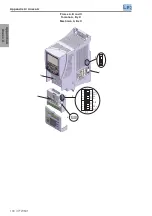
Page 134: ...4 Plug in module 5 HMI 6 Front Cover 1 Soporte de fijaci n para el montaje en superficie 2 Soporte de fijaci n para el montaje en carril DIN 3 Ventilador con soporte de fijaci n 4 M dulo plug in 5 HM...

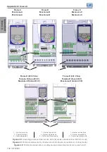
Page 135: ...130 CFW501 Appendix A Anexo A Appendix A Anexo A Frame A B and C Tama o A B y C Mec nica A B e C 3 4 2 5 6 1 S1 AI1 1 1 2 2 3 3 4 4 AO1 B A AI2 B2 A2 S2 ON DIP ON DIP NC...

Page 136: ...cci n del tipo de se al de las entradas y salidas anal gicas y resistores de la terminaci n RS485 4 Llave de aterramiento de los capacitores de filtro RFI 5 Etiqueta de identificaci n de las funciones...

Page 137: ...V 3 2 1 1 Control terminals 2 Power terminals 3 Grounding points 1 Bornes de control 2 Bornes de potencia 3 Puntos de aterramiento 1 Bornes de controle 2 Bornes de pot ncia 3 Pontos de aterramento Fi...

Page 138: ...3 MPW18 3 D063 1 5 16 2 5 14 CFW501A07P0T2 7 0 2 1 5 680 20 FNH00 20K A 10 MPW18 3 U010 1 5 16 2 5 14 CFW501A09P6T2 9 6 3 2 2 1250 25 FNH00 25K A 16 MPW18 3 U016 2 5 14 2 5 14 CFW501B07P3T2 B 7 3 2 1...

Page 139: ...em em Superf cie Inom 1 min 3 s fsw Arms Arms Arms kHz Arms W CFW501A01P6T2 1 6 1 8 2 4 5 50 122 40 104 1 50 13 CFW501A02P6T2 2 6 2 9 3 9 5 50 122 40 104 2 42 18 CFW501A04P3T2 4 3 4 7 6 5 5 50 122 40...

Page 140: ...ncy is 5 kHz for models 1 2 3 4 5 6 7 8 9 10 11 12 and 13 For conducted emission category C3 in models 1 2 3 4 5 6 7 8 and 9 use the ferrite 12480705 on the output cables 2 turns and use the ferrite 1...

Page 141: ...4 3 A 2 9 A 2 0 A CFW501B06P5T4 6 5 A 6 5 A 4 5 A 3 3 A CFW501B10P0T4 10 A 10 A 6 5 A 4 3 A CFW501C14P0T4 14 A 14 A 10 A 7 A CFW501C16P0T4 16 A 16 A 10 A 7 A CFW501D24P0T4 24 A 24 A 15 A 12 A CFW501D3...

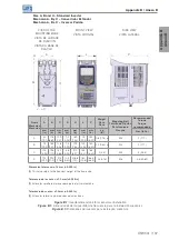
Page 142: ...91 0 8 1 76 1 M4 2 17 7 B 75 2 95 185 7 30 11 8 0 46 7 3 0 29 199 7 83 100 3 94 160 6 30 1 2 2 65 1 M4 2 17 7 C 100 3 94 195 7 70 16 7 0 66 5 8 0 23 210 8 27 135 5 31 165 6 50 2 4 4 M5 3 26 5 D 125 4...

Page 143: ...to mount inverters side by side without lateral free space D 0 however with maximum ambient temperature of 40 C Tolerancia de las cotas 1 0 mm 0 039 in 1 Es posible montar convertidores lado a lado si...

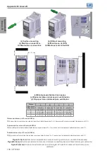
Page 144: ...A Mec nica A Mec nica A Frame B Mec nica B Mec nica B Frame C Mec nica C Mec nica C Frame D models 200 240 V Tama o D los modelos 200 240 V Mec nica D modelos 200 240 V Frame D models 380 480 V Tama...

Page 145: ...in N m Lbf in A 200 240 V 0 5 4 34 0 5 4 34 380 480 V 0 5 4 34 0 5 4 34 B 200 240 V 0 5 4 34 0 5 4 34 380 480 V 0 5 4 34 0 5 4 34 C 200 240 V 0 5 4 34 1 7 15 00 380 480 V 0 5 4 34 1 8 15 93 D 200 240...

Page 146: ...12 6 0 5 11 9 0 5 50 2 5 4 0 2 5 6 0 2 189 1 7 4 175 6 9 7 7 0 3 86 6 3 4 75 2 3 149 5 5 9 81 3 2 50 2 A A B B 77 3 41 7 1 6 Figure B 4 Inverter dimensions in mm in frame A Figura B 4 Dimensiones del...

Page 147: ...2 6 0 5 11 8 0 5 75 3 5 4 0 2 5 6 0 2 B A B 199 1 7 8 185 7 3 7 1 0 3 96 5 3 8 75 3 160 1 6 3 91 3 6 100 2 3 9 87 3 4 46 7 1 8 Figure B 5 Inverter dimensions in mm in frame B Figura B 5 Dimensiones de...

Page 148: ...0 7 100 3 9 6 4 0 3 6 2 0 2 B A B 210 8 3 195 7 7 9 7 0 4 106 1 4 2 100 3 9 165 1 6 5 96 3 8 135 2 5 3 92 3 6 46 7 1 8 16 7 0 7 A Figure B 6 Inverter dimensions in mm in frame C Figura B 6 Dimensione...

Page 149: ...0 4 99 6 3 9 125 4 9 166 4 6 6 86 7 3 4 180 7 1 84 3 3 42 6 1 7 125 4 9 5 9 0 2 8 0 3 26 8 1 1 26 8 1 1 7 2 0 3 7 2 0 3 B 10 1 0 4 A Figure B 7 Inverter dimensions in mm in frame D Figura B 7 Dimensio...

Reviews: