12
Functions Common to all the Control Modes
12-2 | CFW700
open
open
24 V
Time
24 V
Time
P0102
P0100
DIx -
Run/Stop
2
nd
ramp DIx
Motor Speed
P0103
P0101
Time
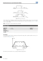
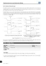
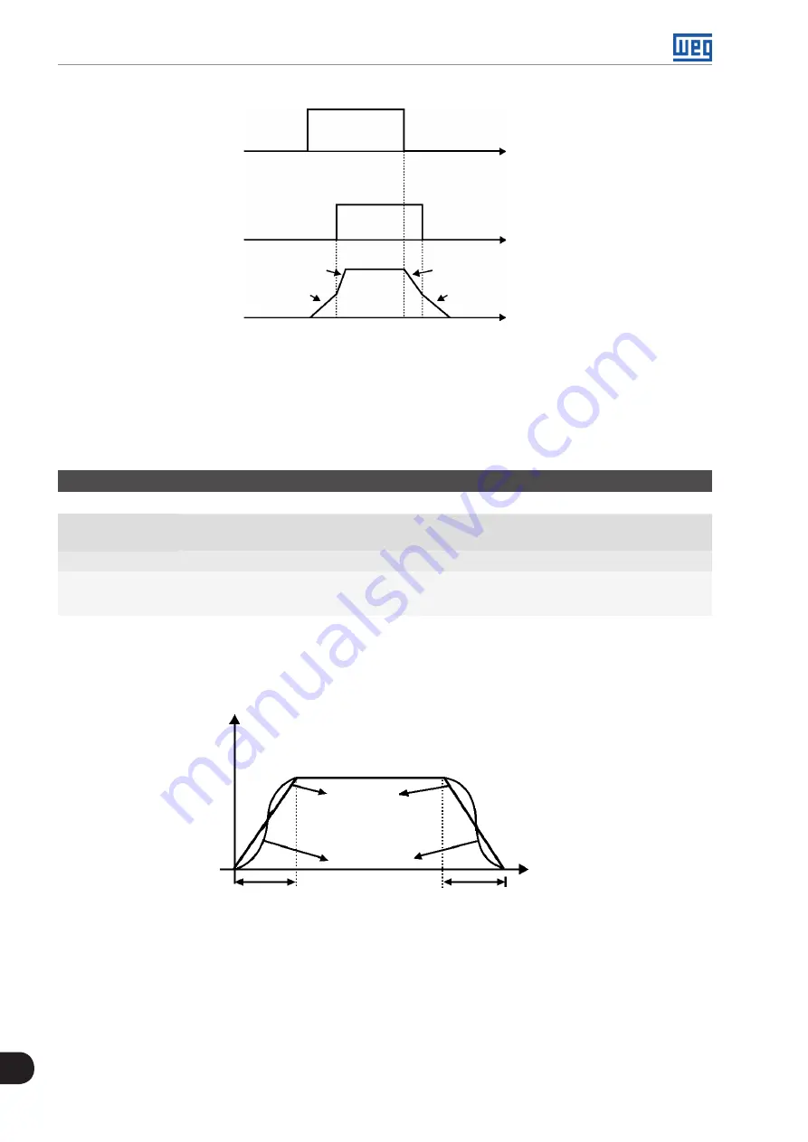
Figure 12.1:
Second ramp actuation
In this example, the commutation to the 2nd ramp (P0102 or P0103) is done by means of one of the digital
inputs from DI1 to DI8, provided that it had been programmed for 2nd ramp function (refer to
, for more details).
Note:
The setting 0.0 s means that the ramp is disabled.
P0104 – Ramp
Adjustable
Range:
0 = Linear
1 = S Curve
Factory
Setting:
0
Properties:
Access groups
via HMI:
Description:
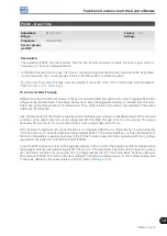
This parameter allows that the acceleration and deceleration ramps have a nonlinear profile, similar to an “S”,
as showed in the
next.
Deceleration Time
(P0101/P0103)
Acceleration Time
(P0100/P0102)
t (s)
S Ramp
Linear
Speed
Figure 12.2:
S or linear ramp
The S ramp reduces mechanic shock during accelerations/decelerations.
Summary of Contents for CFW700
Page 2: ......
Page 4: ......
Page 8: ...Summary...
Page 34: ...2 General Information 2 4 CFW700...
Page 38: ...3 About the CFW700 3 4 CFW700...
Page 56: ...7 Starting up and Settings 7 4 CFW700...
Page 58: ...8 Available Control Types 8 2 CFW700...
Page 78: ...10 VVW Control 10 8 CFW700...
Page 158: ...13 Digital and Analog Inputs and Outputs 13 28 CFW700...

