16
Read only Parameters
16-10 | CFW700
P0094 – Last Fault Frequency
Adjustable
Range:
0.0 to 1020.0 Hz
Factory
Setting:
Properties:
ro
Access groups
via HMI:
READ
Description:
It is the record of the inverter output frequency at the moment of the last fault occurrence.
P0095 – Last Fault Motor Voltage
Adjustable
Range:
0 to 2000 V
Factory
Setting:
Properties:
ro
Access groups
via HMI:
READ
Description:
It is the record of the motor voltage at the moment of the last fault occurrence.
P0096 – Last Fault DIx Status
Adjustable
Range:
Bit 0 = DI1
Bit 1 = DI2
Bit 2 = DI3
Bit 3 = DI4
Bit 4 = DI5
Bit 5 = DI6
Bit 6 = DI7
Bit 7 = DI8
Factory
Setting:
Properties:
ro
Access groups
via HMI:
READ
Description:
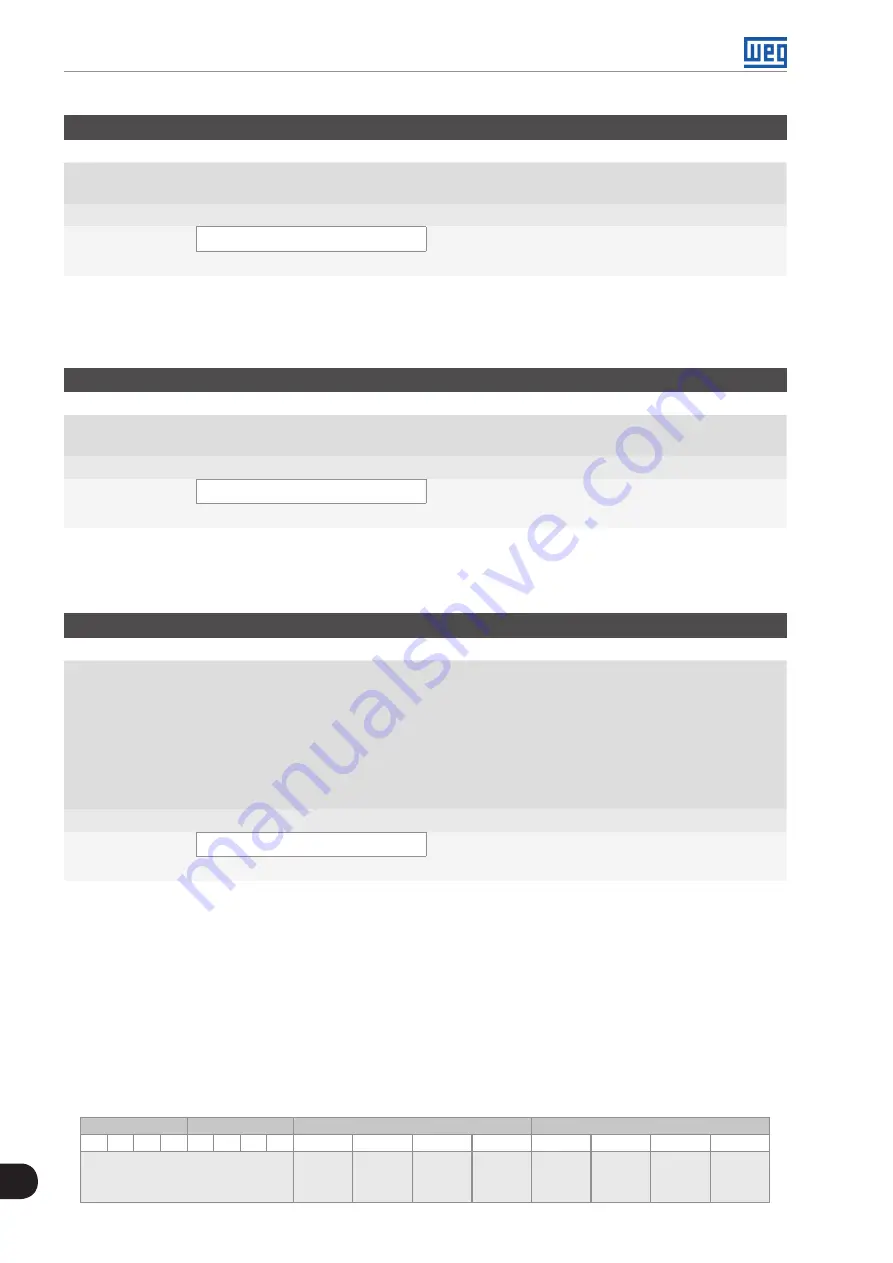
It indicates the state of the digital inputs at the moment of the last fault occurrence.
The indication is done by means of an hexadecimal code, which when converted to binary will indicate the
states “active” and “inactive” of the inputs through numbers 1 and 0.
Example: If the code presented for the parameter P0096 on the keypad (HMI) is 00A5, it will correspond to
the sequence
10100101
, indicating that the inputs 8, 6, 3 and 1 were active at the moment of the last fault
occurrence.
Table 16.2:
Example of correspondence between the P0096 hexadecimal code and the DIx states
0
0
A
5
0
0
0
0
0
0
0
0
1
0
1
0
0
1
0
1
No relation with the DIx
(always zero)
DI8
Active
(+24 V)
DI7
Inactive
(0 V)
DI6
Active
(+24 V)
DI5
Inactive
(0 V)
DI4
Inactive
(0 V)
DI3
Active
(+24 V)
DI2
Inactive
(0 V)
DI1
Active
(+24 V)
Summary of Contents for CFW700
Page 2: ......
Page 4: ......
Page 8: ...Summary...
Page 34: ...2 General Information 2 4 CFW700...
Page 38: ...3 About the CFW700 3 4 CFW700...
Page 56: ...7 Starting up and Settings 7 4 CFW700...
Page 58: ...8 Available Control Types 8 2 CFW700...
Page 78: ...10 VVW Control 10 8 CFW700...
Page 158: ...13 Digital and Analog Inputs and Outputs 13 28 CFW700...


