Applications
19
CFW700 | 19-5
5. Setting the PID setpoint:
The PID setpoint can be set via the keypad, analog inputs, serial interface or network as available at P1016.
The setpoint is selected via the keypad (P1016 = 0) in this guide. Therefore, the PID setpoint value will be set
via parameter P1025 according to the following equation:
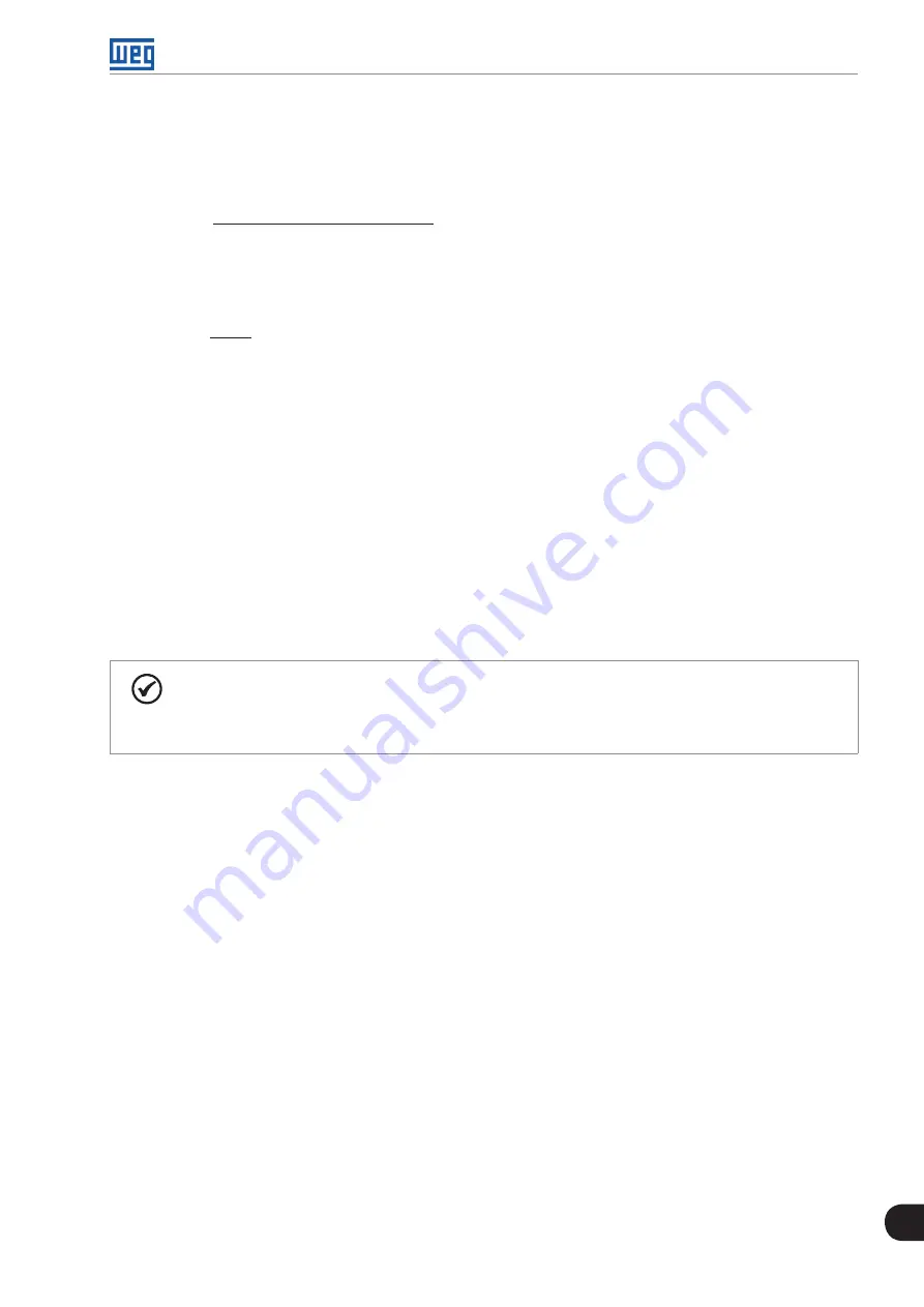
Setpoint (%) =
Desired value (process variable)
x 100.0 %
PID feedback sensor full scale
Example: a 4-20 mA pressure transducer with 25 bar output full scale (i.e. 4 mA = 0 bar and 20 mA = 25 bar),
P0237 = 1.000 and P0239 = 0.00 %. If it is necessary to control 20.0 bar, the following setpoint should be set:
Setpoint (%) =
20.0
x 100.0 % = 80.0 %
25.0
6. Setting the PID regulator action type:
The action type must be direct (P1024 = 0) when it the motor speed is increased to increase the process
variable. Otherwise, select reverse (P1024 = 1).
Examples:
a) Direct: a pump driven by an inverter is filling a reservoir and the PID control is regulating the level of this reservoir.
In order to increase the level (process variable), the flow needs to be increased by increasing the motor speed.
b) Reverse: a fan driven by an inverter is cooling a cooling tower and the PID control is regulating the temperature
of this cooling tower. In order to increase the temperature (process variable), it is necessary to reduce the
ventilation by reducing the motor speed.
7. Setting the speed reference:
When the PID regulator application operates in local mode, P0221 must be set to 7 = SoftPLC. When the PID
regulator application operates in remote mode, P0222 must be set to 7 = SoftPLC.
NOTE!
If the PID regulator application has been selected to operate in local mode and the DI1 (P0263) has
been selected to Manual/Auto command, the inverter will go to the “configuration (CONF)” state and
it will be necessary to change the default setting of P0227.
8. Speed Limits:
Set P0133 and P0134 according to the application remembering that the PID controller is designed to work
with inputs and outputs referenced from 0.0 to 100.0 %. This output value is converted to operate in the range
set at P0133 and P0134 in order to avoid speed ranges where there is no contribution to the control of the
process variable.
9. Setting the reading parameters of the keypad monitoring screen:
The monitoring mode screen of the CFW700 keypad can be configured to display the control variables of the
PID regulator in numerical form. The example below was chosen to show the PID feedback or the process
variable, the PID setpoint and motor speed.
Example:
a) Reading parameter 1 to show the process variable:
- Set P0205 to 1012 which corresponds to the P1012 parameter of the PID regulator application.
- Set P0208 to 100.0 %.
- Set P0209 to 0 (none).
- Set P0210 to 1 (wxy.z).
b) Reading parameter 2 to show the PID setpoint:
- Set P0206 to 1011 which corresponds to the P1011 parameter of the PID regulator application.
- Set P0211 to 100.0 %.
- Set P0212 to 1 (wxy.z).
Summary of Contents for CFW700
Page 2: ......
Page 4: ......
Page 8: ...Summary...
Page 34: ...2 General Information 2 4 CFW700...
Page 38: ...3 About the CFW700 3 4 CFW700...
Page 56: ...7 Starting up and Settings 7 4 CFW700...
Page 58: ...8 Available Control Types 8 2 CFW700...
Page 78: ...10 VVW Control 10 8 CFW700...
Page 158: ...13 Digital and Analog Inputs and Outputs 13 28 CFW700...


