6
Inverter Model and Accessories Identification
CFW700 | 6-1
6 INVERTER MODEL AND ACCESSORIES IDENTIFICATION
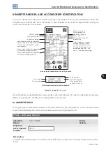
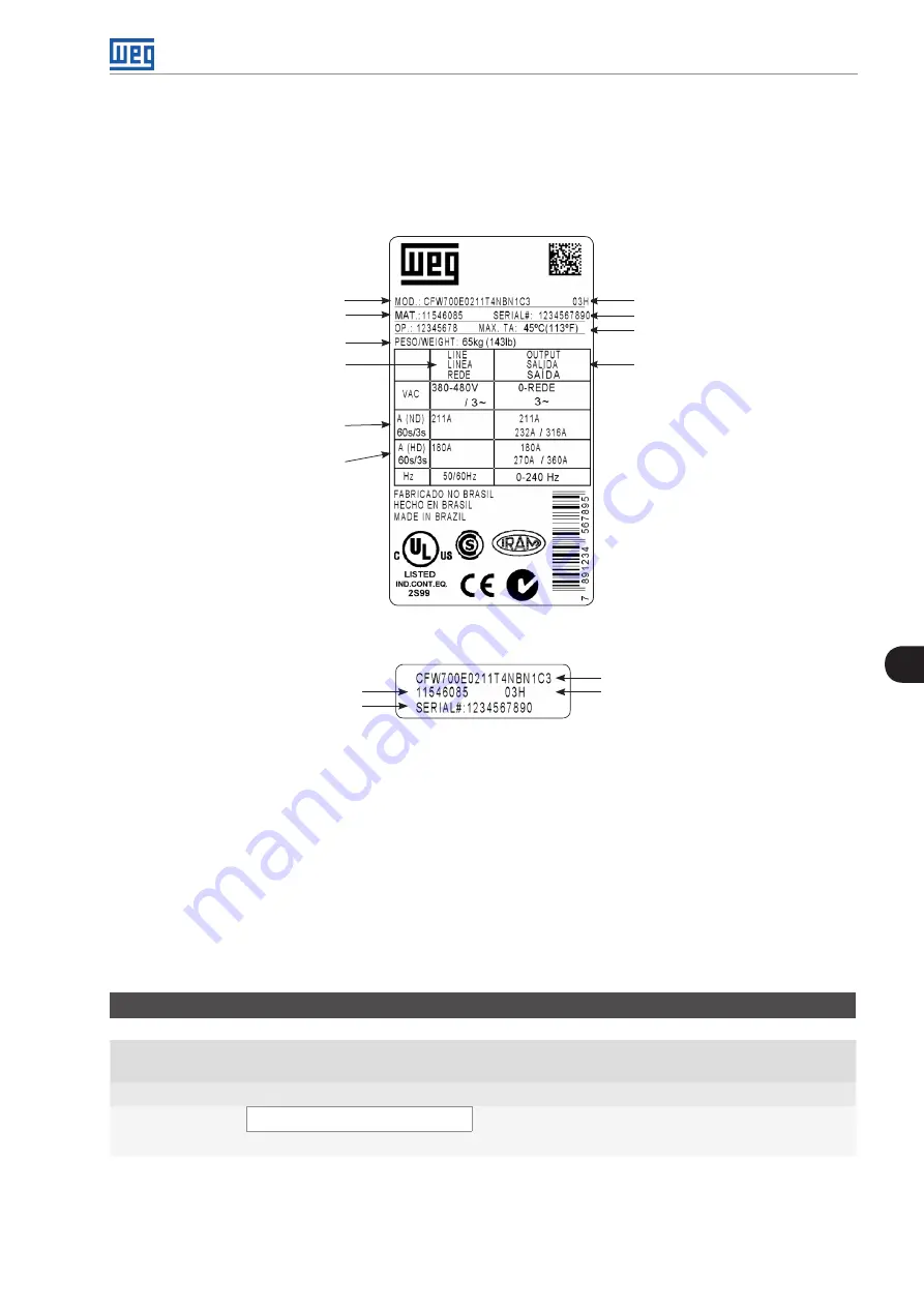
In order to identify the model of the inverter, verify the code existent on the product identification labels: the
complete one, located at the side of the inverter, or the abbreviated one, under the keypad (HMI). The figures
below show examples of those labels.
CFW700 model
WEG part number
Manufacturing date
(03 corresponds to
week and H to year)
Inverter net weight
Input rated data (voltage, number of
phases, rated currents for operation
with ND and HD overload cycles,
and frequency)
Output rated data (voltage,
number of phases, rated
currents for operation with
ND and HD overload cycles,
overload currents for 1 min
and 3 s, and frequency range)
Maximum environment
temperature
Serial number
Current specifications for operation
with normal overload cycle (ND)
Current specifications for operation
with heavy overload cycle (HD)
(a) Nameplate affixed to the side of the inverter
CFW700 model
Part number
Manufacturing date
(03 corresponds to
week and H to year)
Serial number
(b) Nameplate located under the keypad
Figure 6.1 (a) and (b):
Nameplates
Once the inverter model identification code is verified, one must interpret it in order to understand its meaning.
Refer to the section 2.3 - Identification, of the CFW700 user's manual.
6.1 INVERTER DATA
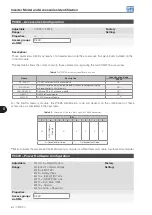
In this group are the parameters related to the inverter information and characteristics, such as inverter model,
accessories identified by the control circuit, software version, switching frequency, etc.
P0023 – Software Version
Adjustable
Range:
0.00 to 655.35
Factory
Setting:
Properties:
ro
Access groups
via HMI:
READ
Description:
It indicates the software version contained in the FLASH memory of the microcontroller located on the control
board.
Summary of Contents for CFW700
Page 2: ......
Page 4: ......
Page 8: ...Summary...
Page 34: ...2 General Information 2 4 CFW700...
Page 38: ...3 About the CFW700 3 4 CFW700...
Page 56: ...7 Starting up and Settings 7 4 CFW700...
Page 58: ...8 Available Control Types 8 2 CFW700...
Page 78: ...10 VVW Control 10 8 CFW700...
Page 158: ...13 Digital and Analog Inputs and Outputs 13 28 CFW700...

