6
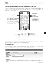
Inverter Model and Accessories Identification
CFW700 | 6-3
Description:
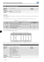
In a similar way than parameters P0028, the parameter P0029 identifies the inverter model and the present
accessories.
The codification is formed by the combination of binary digits, and presented in the keypad (HMI) in hexadecimal
format.
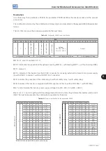
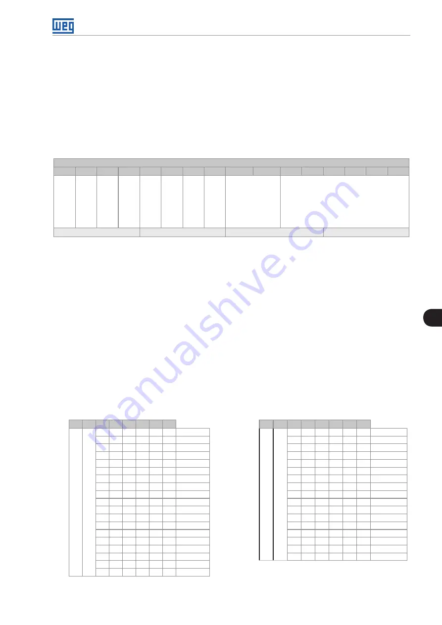
The bits that compose the code are explained in the next table.
Table 6.3:
Parameter P0029 code constitution
Bits
15
14
13
12
11
10
9
8
7
6
5
4
3
2
1
0
1
1
0
w
ith b
ra
ki
ng I
G
B
T
0
w
ith 2
4 V s
up
pl
y
w
ith s
af
et
y r
el
ay
w
ith R
FI fi
lte
r
Voltage
00=200…240 V
01=380…480 V
Current
4th Hexadecimal Code
3rd Hexadecimal Code
2nd Hexadecimal Code
1st Hexadecimal Code
Bits 15, 14 and 13: are fixed in 110.
Bit 12: it indicates the presence of the dynamic braking IGBT (0 = with braking IGBT, 1 = without braking IGBT).
Bit 11: always 0.
Bit 10: indicates if the inverter has the DC/DC converter for receiving external 24 V electronics power supply
(0=with DC/DC converter, 1=without DC/DC 24 V converter).
Bit 9: indicates the presence of the safety relay (0=without safety relay, 1=with safety relay).
Bit 8: indicates if the inverter is equipped with RFI suppressor filter (0=without RFI filter, 1=with RFI filter).
Bits 7 and 6: indicate the inverter power supply voltage (00=200...240 V, 01=380…480 V).
Bits 5, 4, 3, 2, 1 and 0: together with the voltage indication bits (7 and 6), they indicate the inverter rated current
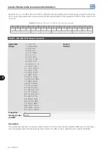
(ND). The next table presents the combinations available for those bits.
Table 6.4:
Current codification for the parameter P0029
7
6
5
4
3
2
1
0
7
6
5
4
3
2
1
0
20
0 V
...
24
0 V
0
0
0
0
0
0
0
0
2 A*
38
0 V
...
48
0 V
0
1
0
0
0
0
0
0
3.6 A
0
0
0
0
0
1
6 A*
0
0
0
0
0
1
5 A
0
0
0
0
1
0
7 A*
0
0
0
0
1
0
7 A
0
0
0
0
1
1
10 A*
0
0
0
1
0
0
10 A
0
0
0
1
0
0
7 A
0
0
0
1
0
1
13.5 A
0
0
0
1
0
1
10 A
0
0
1
0
0
0
17 A
0
0
0
1
1
0
13 A
0
0
0
1
1
0
24 A
0
0
0
1
1
1
16 A
0
0
0
1
1
1
31 A
0
0
1
0
0
0
24 A
0
0
0
0
1
1
38 A
0
0
1
0
0
1
28 A
0
0
1
0
1
0
45 A
0
0
1
0
1
0
33.5 A
0
0
1
0
1
1
58.5 A
0
0
1
1
0
0
45 A
0
0
1
1
0
0
70.5 A
0
0
1
1
0
1
54 A
0
0
1
1
0
1
88 A
0
0
1
1
1
0
70 A
0
1
0
0
0
0
105 A
0
1
0
0
0
0
86 A
0
1
0
0
0
1
142 A
0
1
0
0
0
1
105 A
0
1
0
0
1
0
180 A
0
1
0
0
1
0
180 A
0
1
0
0
1
1
211 A
0
1
0
0
1
1
211 A
0
1
0
1
0
0
142 A
* Models with single-phase/three-phase power supply.
Summary of Contents for CFW700
Page 2: ......
Page 4: ......
Page 8: ...Summary...
Page 34: ...2 General Information 2 4 CFW700...
Page 38: ...3 About the CFW700 3 4 CFW700...
Page 56: ...7 Starting up and Settings 7 4 CFW700...
Page 58: ...8 Available Control Types 8 2 CFW700...
Page 78: ...10 VVW Control 10 8 CFW700...
Page 158: ...13 Digital and Analog Inputs and Outputs 13 28 CFW700...

