Vector Control
11
CFW700 | 11-5
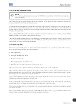
11.2 I/f MODE (SENSORLESS)
NOTE!
It is activated automatically at low speeds if P0182>3 and when the Control Mode is Sensorless
Vector (P0202=4).
The operation at the low speed region may present instability. In this region the motor operation voltage is also
very low, being difficult to be measured accurately.
In order to keep a stable operation of the inverter in that region, the automatic commutation occurs, from sensorless
mode to the so called I/f mode, which is a scalar control with imposed current. Scalar control with imposed
current means a current control with a constant reference value, adjusted in a parameter and controlling only the
frequency in an open loop.
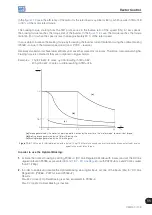
The parameter P0182 defines the speed below which the transition to I/f mode occurs and the parameter P0183
defines the value of the current to be applied to the motor.
The minimum speed recommended for the operation of the Sensorless Vector Mode is 18 rpm for 60 Hz IV pole
motors, and 15 rpm for 50 Hz IV pole motors. If P0182 ≤ 3 rpm the inverter will always operate in Sensorless
Vector mode, i.e., the I/f function will be disabled.
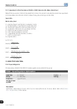
11.3 SELF-TUNING
Some motor parameters that are not available on the motor nameplate, necessary for the operation of the sensorless
vector or vector with encoder control, are estimated:
Stator resistance.
Motor flux leakage inductance.
Rotor time constant T
r
.
Rated magnetizing current of the motor.
Mechanic time constant of the motor and the driven load.
These parameters are estimated with the application of voltages and currents to the motor.
The parameters related to the regulators used by the vector control, as well as other control parameters, are
adjusted automatically in function of the motor parameters estimated through the self-tuning routine. The best
self-tuning results are obtained with a preheated motor.
The parameter P0408 controls the self-tuning routine. Depending on the chosen option some parameters can be
obtained from tables that are valid for WEG motors.
In the option P0408=1 (No Rotation) the motor remains stopped throughout the self-tuning. The magnetizing
current value (P0410) is obtained from a table, valid for WEG motors up to 12 poles.
In the option P0408=2 (Run for I
m
) the value of P0410 is estimated with the motor rotating and the load decoupled
from the motor shaft.
In the option P0408=3 (Run for T
m
) the value of P0413 (Mechanic time constant – T
m
) is estimated with the motor
rotating. It must be done, preferably, with the load coupled to the motor.
Summary of Contents for CFW700
Page 2: ......
Page 4: ......
Page 8: ...Summary...
Page 34: ...2 General Information 2 4 CFW700...
Page 38: ...3 About the CFW700 3 4 CFW700...
Page 56: ...7 Starting up and Settings 7 4 CFW700...
Page 58: ...8 Available Control Types 8 2 CFW700...
Page 78: ...10 VVW Control 10 8 CFW700...
Page 158: ...13 Digital and Analog Inputs and Outputs 13 28 CFW700...


