Vector Control
11
CFW700 | 11-9
In the
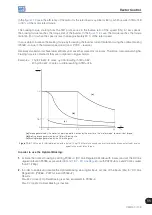
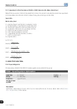
case, the efficiency of the motor for the rated load is
η
=0.84 (or 84 %), which results in TB1=0.19
or 19 % of the motor rated torque.
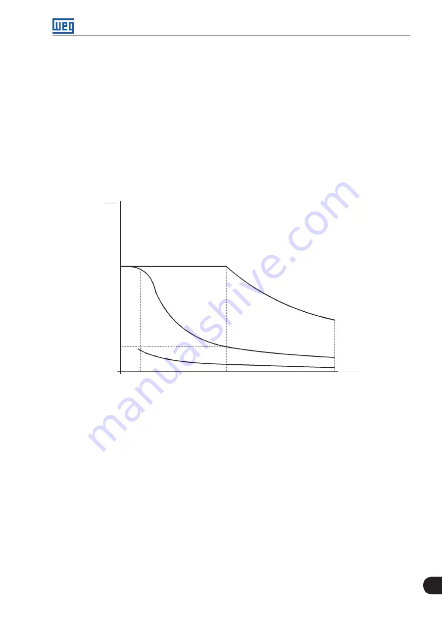
The braking torque, starting from the TB1 point, varies in the inverse ratio of the speed (1/N). At low speeds,
the braking torque reaches the torque limit of the inverter. In the
case, the torque reaches the torque
limitation (100 %) when the speed is less than approximately 20 % of the rated speed.
It is possible to increase the braking torque by increasing the inverter current limitation during the optimal braking
(P0169 – torque in the forward speed direction or P0170 – reverse).
Generally smaller motors have lower efficiency because they present more losses. Therefore, comparatively higher
braking torque is obtained if they are compared to bigger motors.
Examples: 1 hp/0.75 kW, IV poles:
η
=0.76 resulting in TB1=0.32;
20 hp/15.0 kW, IV poles:
η
=0.86 resulting in TB1=0.16.
T
T
nom
N
N
nom
TB1
1.0
0
0
0.2
1.0
2.0
(c)
(b)
(a)
(a)
Torque generated by the motor in normal operation, driven by the inverter in the “motor mode” (load resistant torque).
(b)
Braking torque generated by the Optimal Braking use.
(c)
Braking torque generated by the DC braking use.
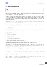
Figure 11.3:
T x N curve for Optimal Braking with a typical 10 hp/7.5 kW motor, driven by an inverter with the torque adjusted at a value
equal to the motor rated torque
In order to use the Optimal Braking:
1.
Activate the optimal braking by setting P0184=0 (DC Link Regulation Mode=with losses) and set the DC link
regulation level in P0185, as presented in
item 11.8.7 - DC Link Regulator
, with P0202=5 or 4 and P0404 smaller
than 21 (75hp).
2.
In order to enable and disable the Optimal Braking via a digital input, set one of the inputs (DIx) for “DC Link
Regulation”. (P0263…P0270=16 and P0184=2).
Results:
DIx=24 V (closed): Optimal Braking is active, equivalent to P0184=0.
DIx=0 V (open): Optimal Braking is inactive.
Summary of Contents for CFW700
Page 2: ......
Page 4: ......
Page 8: ...Summary...
Page 34: ...2 General Information 2 4 CFW700...
Page 38: ...3 About the CFW700 3 4 CFW700...
Page 56: ...7 Starting up and Settings 7 4 CFW700...
Page 58: ...8 Available Control Types 8 2 CFW700...
Page 78: ...10 VVW Control 10 8 CFW700...
Page 158: ...13 Digital and Analog Inputs and Outputs 13 28 CFW700...


