English
TECHNICAL SPECIFICATIONS
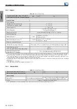
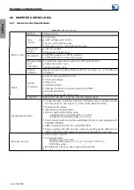
8.3.2 Input and Output Specifications
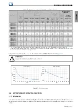
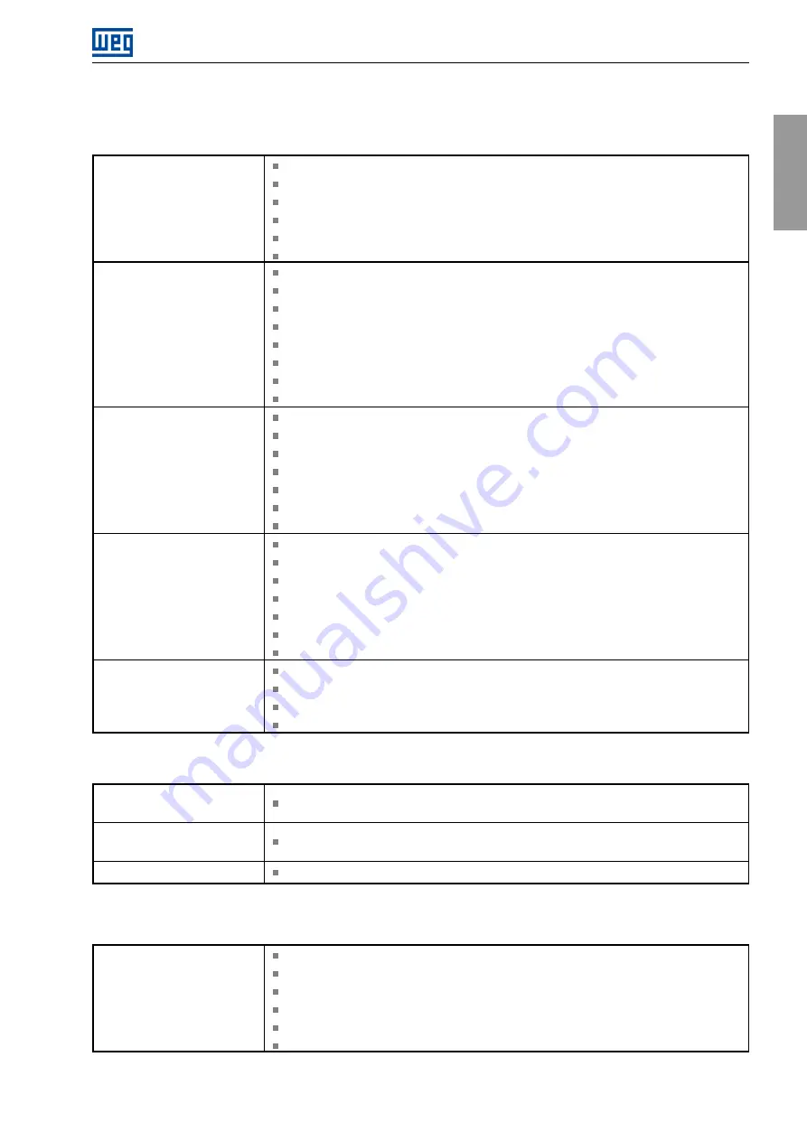
Table 8.11:
Characteristics of analog and digital inputs and outputs (XC1)
Digital input DI1 to DI4
4 isolated digital inputs.
Low level: Vdc -3 V to 5 V, I<1,5 mA.
High level: Vdc > 11 V, I>2 mA.
Current 8mA@24V (Typical).
Maximum voltage: 30 Vdc.
Maximum current: 11mA@30Vdc.
Digital input DI5 and DI6
2 isolated digital inputs.
Low level: Vdc -3 V to 5 V, I<0,5 mA.
High level: Vdc > 15 V, I>2 mA.
Current 10mA@24V (Typical).
Maximum voltage: 30 Vdc.
Maximum current: 13mA@30Vdc.
Maximum frequency: 32 kHz.
Input for encoder signals (maximum cable length of 3 m).
Analog inputs
2 differential analog inputs.
Isolated from power circuits.
Levels: -10/0 at 10 V (11 bits + signal), 0/4 at 20 mA (10 bits).
Maximum voltage: 30 V.
Maximum current: 25 mA.
Impedance: 400 kΩ (voltage mode), 250 Ω (current mode).
Maximum common mode voltage: 10 V.
Digital outputs
2 transistor digital outputs (NPN).
Isolated from power circuits.
Maximum current: 40 mA.
Protected against short circuit to the GND.
Maximum voltage: 24 Vdc.
With freewheeling diode for 24 Vdc power supply.
Maximum frequency: 32 kHz.
Analog outputs
2 analog outputs.
Isolated from power circuits.
Levels: 0 at 10 V (12 bits), 0/4 at 20 mA (12 bits).
Load:
R
L
≥
1
k
Ω
(voltage mode),
R
L
≤
600Ω
(current mode).
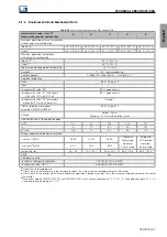
Table 8.12:
Characteristics of the inputs and outputs of the internal safety module (XC2)
STO1 and STO2 Digital
Input
Redundant inputs for OSSD signals or dry contact signals.
SP1 and SP2 test digital
output
Outputs to power dry contact.
24VS power supply input
Input for 24 V power supply
±
15% to the internal safety module.
*For more details, see the safety manual.
Table 8.13:
Characteristics of the CFW900-REL-01 (XC30)
Relay output
2 relay outputs with NO contact.
1 relay output with NO/NC contact.
Maximum voltage: 30 Vdc, 250 Vac, OVC III.
Maximum current: 2 A.
Minimum current: 10 mA@5 Vdc.
400 V TVS between contacts.
CFW900 | 107
Summary of Contents for CFW900
Page 2: ......


