


English
GENERAL INFORMATION
XC2
1
1
2
?
JOG
LOC
REM
A
B
G
F
E
D
C
2
?
JOG
LOC
REM
1
XC1
XC1
XC4
?
JOG
LOC
REM
XC6
XC3
XC30
R/L1
S/L2
T/L3
U/T1
V/T2
W/T3
Power and Control
DC+
BR
Braking Resistor
DC-
Connection to the DC link
Connection to the braking
resistor
Inverter Circuit
Rectifier
and
Pre-charge
RFI Filter/
Varistors (*)
Screw
Link
Inductor
Link
Capacitor
RFI
filter
Screw
Braking
IGBT
PE
SP1, SP2
STO1,STO2
Safety module:
STO/SS1-t functions
Control and Monitoring
Module
Safety
device
Interface
Remote HMI
Smartphone
with WEG WPS
PC
CFW900
ED300
CLP
Ethernet
dual port
USB
MicroSD
card
(not included)
MicroSD
card slot
RTC
CR2032
battery
Application
module
and
user
interface
CFW900-4SLOTS
(included)
Backplane
with
4
expansion
slots
CFW900-7SLOTS
(optional)
7
expansion
slots
Slots:
Accessories
CFW900-REL-01
(included)
DO1-A-NA/NF
DO2-A-NA
DO3-A-NA
Optional
Optional
Optional
Optional
Optional
Optional
DI1-X...DI6-X
External 24 V
Power Supply
(backup)
AI1-X
AI2-X
Protection
XC1
CFW900-IOS
Protection
Protection
Lettering
Not included
Alternative wiring
Isolation
DO1-X
DO2-X
24V, 0,8A
10V, 10mA
AO1-X
AO2-X
Connectors
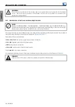
(*) All models have a built-in RFI filter.
Figure 2.1:
Block diagram for the CFW900
6 | CFW900
Summary of Contents for CFW900
Page 2: ......


