


English
GENERAL INFORMATION
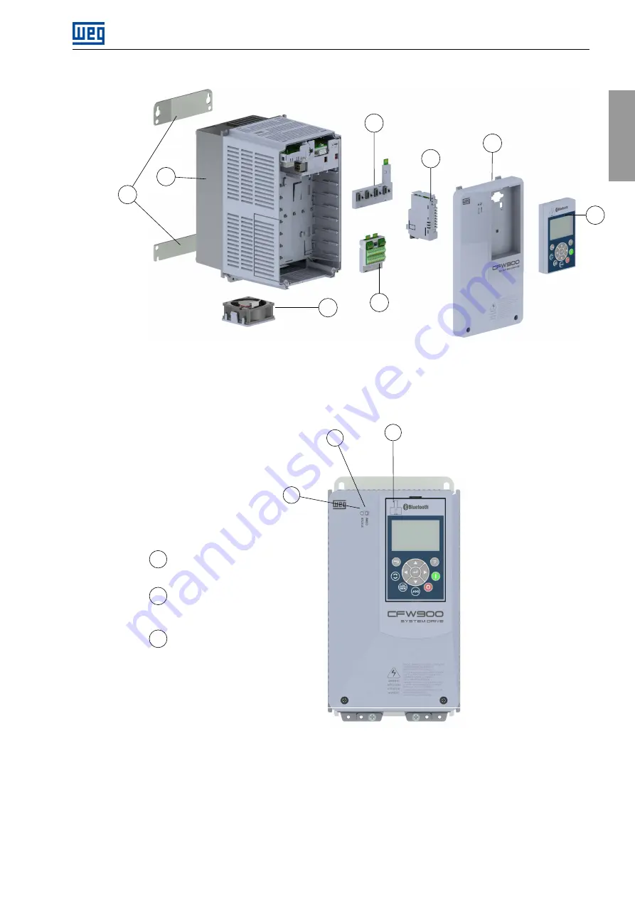
A - surface mount brackets
B - heatsink/back of inverter
C - fan with mounting bracket
D - XC1 connector (CFW900-IOS)
E - CFW900-4SLOTS backplane
F - CFW900-REL accessory board module
G - front cover
H - HMI
A
B
C
D
E
F
G
H
Figure 2.2:
Main components
2
3
1
1
2
3
USB Connector
Communication LED
Off: communication inactive
On/flashing: communication active
Status LED
Green: normal operation
Yellow: alarm condition
Red: protection tripping condition
Figure 2.3:
LEDs and USB connector
CFW900 | 7
Summary of Contents for CFW900
Page 2: ......


