English
INSTALLATION AND CONNECTION
Table 3.2:
Screws for the fixing holes
c2
f3
Torque
(1)
Model
M
M
N.m [lbf.in]
Frame A
M5
M5
5 [44.2]
Frame B
M5
M5
5 [44.2]
Frame C
M6
M6
8.5 [75.2]
Frame D
M8
M8
20 [177]
Frame E
M8
M8
20 [177]
(1)
Recommended torque for inverter fixing
B
A
C
D
D
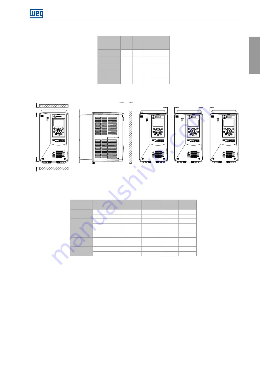
Figure 3.2:
Free clearances for ventilation
Table 3.3:
Free clearances for ventilation
A
B
C
D
Frame Size
Protection
rating
mm [in]
mm [in]
mm [in]
mm [in]
IP20
25 [0.98]
25 [0.98]
10 [0.39]
0 [0]
A
IP21 / UL type 1
25 [0.98]
25 [0.98]
10 [0.39]
30 [1.18]
IP20
40 [1.57]
45 [1.77]
10 [0.39]
0 [0]
B
IP21 / UL type 1
40 [1,57]
45 [1.77]
10 [0.39]
30 [1.18]
IP20
110 [4.33]
130 [5.12]
10 [0.39]
0 [0]
C
IP21 / UL type 1
110 [4.33]
130 [5.12]
10 [0.39]
30 [1.18]
IP20
110 [4.33]
130 [5.12]
10 [0.39]
0 [0]
D
IP21 / UL type 1
110 [4.33]
130 [5.12]
10 [0.39]
30 [1.18]
IP20
150 [5.9]
250 [9.84]
20 [0.79]
0 [0]
E
IP21 / UL type 1
150 [5.9]
250 [9.84]
20 [0.79]
30 [1.18]
3.1.3 Horizontal Mounting
Frames A ... C can be mounted horizontally without derating the output current. The correct mounting position is
shown in
.
CFW900 | 13
Summary of Contents for CFW900
Page 2: ......


