English
INSTALLATION AND CONNECTION
!
WARNING!
The short-circuit protection of the inverter does not provide short-circuit protection for the feeder
circuit. The short-circuit protection of the feeder circuit must be provided in accordance with
applicable local regulations.
3.2.1 Identification of the Power and Grounding Terminals
✓
NOTE!
Models CFW900A04P5B2, CFW900A06P0B2, CFW900A07P3B2 and CFW900A10P0B2 may
operate with single-phase power supply without rated output current derating. In this case, the single-
phase power supply may be connected to two of any input terminals.
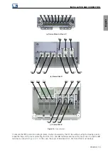
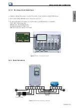
The power terminals can be of different sizes and configurations depending on the inverter model. The location of
the power and grounding connections are indicated in
.
Description of the power terminals:
R/L1, S/L2, T/L3:
AC power supply network cable connection.
DC-/-UD:
negative pole of the DC power supply.
BR:
braking resistor connection.
DC+/+UD:
positive pole of the DC power supply.
U, V and W:
motor cable connection.
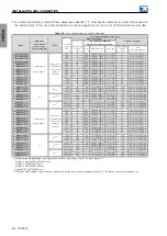
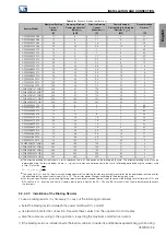
The maximum tightening torque of the power terminals and grounding points must be checked in
.
!
DANGER!
Observe correct DC power connection, polarity and position of the terminals.
18 | CFW900
Summary of Contents for CFW900
Page 2: ......


