English
INSTALLATION AND CONNECTION
R/L1
S/L2
T/L3
DC-
DC+
BR
U/T1
V/T2
W/T3
(a)
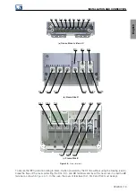
Frame Sizes A, B and C
R/L1
S/L2
T/L3
U/T1
V/T2
W/T3
BR
DC+
DC-
(b)
Frame Size D
DC+
DC-
BR
R/L1
S/L2
T/L3
U/T1
V/T2
W/T3
(c)
Frame Size E
Figure 3.9:
Power terminals
To ensure the IP20 protection rating in frame C when powered by the DC link without using the braking resistor,
break the flaps of the cover protecting the DC+, DC- and BR terminals and insert this new cover to seal the BR
terminal, as shown in
. In this case, the cover of terminals R/L1, S/L2 and T/L3 must be kept.
CFW900 | 19
Summary of Contents for CFW900
Page 2: ......


