English
INSTALLATION AND CONNECTION
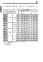
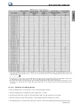
Table 3.8:
Dynamic braking specifications
Inverter Model
Maximum Braking
Current
(Imax)
[A]
Maximum Braking
Power (peak value)
(Pmax)
(2)
[kW]
Effective Braking
Current
(Ieffective)
(1)
[A]
Power (average)
Dissipated in the Braking
Resistor (
P
R
)
(2)
[kW]
Recommended
Resistor
(3)
[Ω]
CFW900A04P5B2
15
6
11
3
27
CFW900A06P0B2
15
6
11
3
27
CFW900A07P3B2
20
8
14
4
20
CFW900A10P0B2
50
20
36
10
8
CFW900A04P5T2
10
4
7
2
40
CFW900A06P0T2
10
4
7
2
40
CFW900A07P3T2
15
6
11
3
27
CFW900A10P0T2
30
12
22
6
13
CFW900A13P0T2
30
12
22
6
13
CFW900A19P0T2
50
20
36
10
8
CFW900B26P0T2
50
20
36
10
8
CFW900B34P0T2
50
20
36
10
8
CFW900B45P0T2
50
20
36
10
8
CFW900C56P0T2
75
30
54
15
5
CFW900C70P0T2
100
40
72
21
4
CFW900C80P0T2
100
40
72
21
4
CFW900D0110T2DB
243
97
174
50
2
CFW900D0135T2DB
243
97
174
50
2
CFW900D0150T2DB
243
97
174
50
2
CFW900E0195T2DB
400
160
287
82
1
CFW900E0250T2DB
400
160
287
82
1
CFW900A02P7T4
10
8
5
2
80
CFW900A04P6T4
10
8
5
2
80
CFW900A06P3T4
10
8
5
2
80
CFW900A09P6T4
15
12
8
1
53
CFW900A14P0T4
25
20
13
5
32
CFW900A17P0T4
35
28
18
7
22
CFW900B26P0T4
25
20
13
5
32
CFW900B33P0T4
25
20
13
5
32
CFW900B39P0T4
75
60
38
16
11
CFW900C49P0T4
75
60
38
16
11
CFW900C60P0T4
75
60
38
16
11
CFW900C70P0T4
150
120
77
32
5
CFW900D90P0T4DB
243
194
124
51
3
CFW900D0123T4DB
243
194
124
51
3
CFW900D0146T4DB
243
194
124
51
3
CFW900E0200T4DB
400
320
205
84
2
CFW900E0240T4DB
400
320
205
84
2
(1)
The effective braking current shown is just a reference value, as it depends on the braking duty cycle. The effective braking current can be
determined using the formula below, where
t
br
is given in minutes and corresponds to the sum of all braking periods during the severest cycle
of five (5) minutes.
I
ef icaz
=
I
max
·
√
t
br
5
(2)
The values of
P
max
and
P
R
(maximum and average power of the braking resistor, respectively) are valid for the recommended resistors and for
the effective braking currents contained in
. The resistor power changes according to the braking duty cycle.
(3)
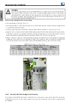
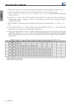
For terminal specifications (screw and tightening torque) and recommended terminal types to connect the braking resistor (terminals DC+ and
BR), see
. Inverters with frame C contain plastic parts in front of the DC-, DC+ and BR terminals, which should be removed to access
the terminals.
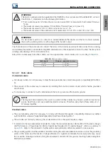
3.2.4.2.2 Installation of the Braking Resistor
To use a braking resistor, it is necessary to carry out the following procedures:
Install the braking resistor between the power terminals DC+ and BR.
Use twisted cable for the connection. Separate these cables from the signal and control cables.
Size the cables according to the application, respecting the maximum and effective currents.
If the braking resistor is installed inside the inverter cabinet, consider its additional dissipated energy when sizing
CFW900 | 33
Summary of Contents for CFW900
Page 2: ......

