


English
INSTALLATION AND CONNECTION
the cabinet ventilation.
!
DANGER!
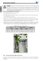
The inverter has an adjustable thermal protection for the braking resistor. The braking transistor and
resistor can be damaged if parameters C3.6.1 (Voltage Level DC Bus) e C3.6.4 (Hysteresis Level)
are not set correctly or if the input voltage exceeds the maximum permissible value.
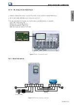
PE
R
S
T
BR DC+
R
S
T
PE
Fuses
Contactor
Thermal Relay
Thermostate
Control Power
Figure 3.14:
Braking resistor connection
✓
NOTE!
DC current flows through the thermal relay bimetal strip during braking.
3.2.4.3 Output Connections
!
WARNING!
The inverter has an electronic motor overload protection that shall be adjusted according to the driven
motor. When several motors are connected to the same inverter, install individual overload relays for
each motor.
34 | CFW900
Summary of Contents for CFW900
Page 2: ......


