English
TROUBLESHOOTING AND MAINTENANCE
6.2 PROTECTIONS, FAULTS, ALARMS, AND POSSIBLE CAUSES
The
Protections, Faults and Alarms
are a functionality of the CFW900 that allows viewing events, helping to
troubleshoot and identifying improvements in the inverter parameter settings.
Protections and faults disable the motor PWM pulses. The reason for their actuation is indicated on the HMI, in
the CFW900 status word ( S1.1.1) and in the current protection diagnosis ( D1.1). This information is only
cleared with a reset or by switching off the inverter.
The alarms are indicated on the HMI, in the CFW900 status word ( S1.1.1) and in the current alarm diagnosis (
D2.1). They are automatically cleared after the alarm condition ceases.
The
Protections, Faults and Alarms
are presented to the user through codes preceded by the letters F for
protection and failure and A for alarm, as shown in the
. In this section you also find more details about
the causes and possible solutions.
✓
NOTE!
Most protections and alarms can be solved by following the instructions contained in this chapter;
otherwise, contact WEG’s representative or technical support.
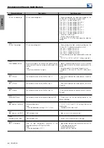
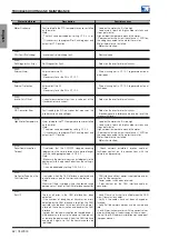
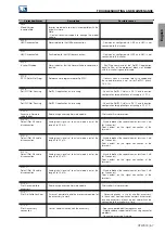
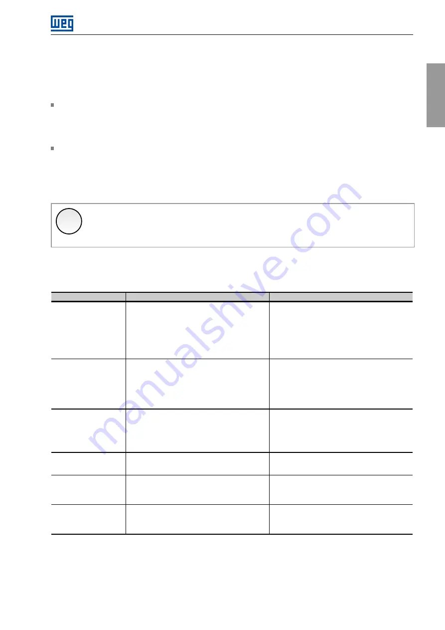
6.3 PROTECTION, FAULT AND ALARM TABLE
Protection/Alarm
Description
Possible causes
F006:
Grid Unbal./Phase Loss
Unbalance or phase loss in the power supply.
Note:
- In case the motor has no load on the shaft or the
load is low, this fault may not occur.
- Actuation time set to C7.1.1. When C7.1.1=0, the
fault is disabled.
- Phase loss at the inverter input.
- Input voltage unbalance >5 %.
- Loss of one phase in the power supply.
A010:
Rectifier Overtemp.
Alarm of high temperature measured in the
temperature sensors (NTC) of the rectifier modules.
Note:
- It can be disabled by changing the IGBT Overtemp.
setting to fault only, in parameter C7.5.1.
- High ambient temperature around the inverter (>50
◦
C) and high output current.
- Locked or defective fan.
- Inverter heat sink too dirty.
F011:
Rectifier Overtemp.
Fault
of
overtemperature
measured
in
the
temperature sensors (NTC) of the rectifier modules.
- High ambient temperature around the inverter (>50
◦
C) and high output current.
- Locked or defective fan.
- Inverter heat sink too dirty.
A018:
Low Battery Voltage
Low battery voltage alarm.
- Replace the battery.
A019:
24Vdc Power Supply
Overvoltage
24Vdc power supply overvoltage fault.
- Voltage of the 24 Vdc power supply that feeds the
control above the maximum value of 27.4 V cc.
A020:
24Vdc Power Supply
Undervoltage
24 Vdc power supply undervoltage fault.
- Voltage of the 24 Vdc power supply that feeds the
control below the minimum value of 22.8 Vdc.
CFW900 | 59
Summary of Contents for CFW900
Page 2: ......


