English
TECHNICAL SPECIFICATIONS
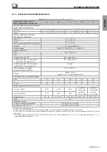
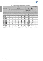
Table 8.8:
Current, power and loss data for T4 line and “HD” overload class
HD overload class:
150% for 60 seconds with a 5-minute interval
200% for 3 seconds with a 5-minute interval
Inverter loss data as
per IEC61800-9-2
(1)
Inverter model
Typical motor
(2)
Dissipated power
for sizing the
panel
Rated
apparent
power
Rated
output
current
380V/60Hz
400V/50Hz
440V/60Hz
460V/60Hz
NEC
Table
460V
Inverter
complete
Front
part
400V
Losses at
rated condition
/
Apparent power
Io,nom (HD)
P,nom
P,nom
P,nom
P,nom
P,nom
PL(inv)
PL(inv2)
So
pL( 90,100)
[Arms]
[CV]
[kW]
[hp]
[hp]
[hp]
[W]
[W]
[kVA]
[%]
CFW900A02P8T4
2.4
1
1.1
1.5
1.5
1
60
29
1.6
3.6%
CFW900A03P6T4
2.8
1.5
1.1
1.5
2
1
61
30
1.9
3.2%
CFW900A04P8T4
3.9
2
1.5
2
3
2
76
31
2.7
2.8%
CFW900A06P5T4
5.3
3
2.2
3
3
3
92
34
3.7
2.5%
CFW900A09P6T4
8
4
3
5
5
5
122
39
5.5
2.2%
CFW900A14P0T4
12
6.0
5.5
7.5
7.5
7.5
172
45
8.3
2.1%
CFW900A17P0T4
17
7.5
7.5
12.5
10
10
236
54
11.8
2.0%
CFW900B26P0T4
21
12.5
11
12.5
15
15
307
74
15.2
2.1%
CFW900B33P0T4
28
12.5
11
20
20
20
342
79
19.4
1.8%
CFW900B39P0T4
33
20
15
20
25
20
397
87
22.8
1.8%
CFW900C50P0T4
40
20
18.5
20
30
30
540
118
28.4
2.0%
CFW900C62P0T4
50
20
22
20
40
30
580
124
34.6
1.7%
CFW900C74P0T4
62
40
30
40
50
40
708
146
42.9
1.7%
CFW900D96P0T4
75
50
37
60
60
50
862
158
51.9
1.7%
CFW900D0124T4
103
60
55
75
75
75
1152
198
71.4
1.7%
CFW900D0146T4
124
75
55
75
100
100
1379
232
85.9
1.7%
CFW900E0172T4
146
100
75
125
125
100
1500
297
101.2
1.5%
CFW900E0203T4
161
100
90
125
125
125
1609
311
108.1
1.5%
CFW900E0242T4
190
125
90
150
150
150
1908
350
131.6
1.5%
(1)
The dissipated power for sizing the panel must be considered the same specified for the ND overload class according to
(2)
Rated power values defined based on the rated current of WEG motors at the indicated voltages.
indicates the maximum inverter
ambient temperature considered for choosing the motor.
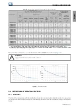
The permissible overload class curve for the inverters of the CFW900 line are shown in
!
WARNING!
Apply one overload every five minutes at most.
100%
120%
140%
160%
180%
200%
220%
240%
0
10
20
30
40
50
60
70
80
90
100
110
120
I
n
o
m
(%)
t (s)
100%
110%
120%
130%
140%
150%
160%
0
10
20
30
40
50
60
70
80
90
100
110
120
I
n
o
m
(%)
t (s)
Normal Duty Cycle
Heavy Duty Cycle
Figure 8.1:
Permissible overload
8.2 DEFINITIONS OF DERATING FACTORS
8.2.1 Introduction
This item of the manual deals with the derating that should be considered when sizing the inverter. In cases where
more than one condition require the output current derating, the factors must be multiplied according to the equation
below:
CFW900 | 101
Summary of Contents for CFW900
Page 2: ......


