English
INSTALLATION AND CONNECTION
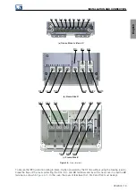
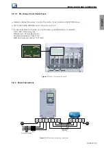
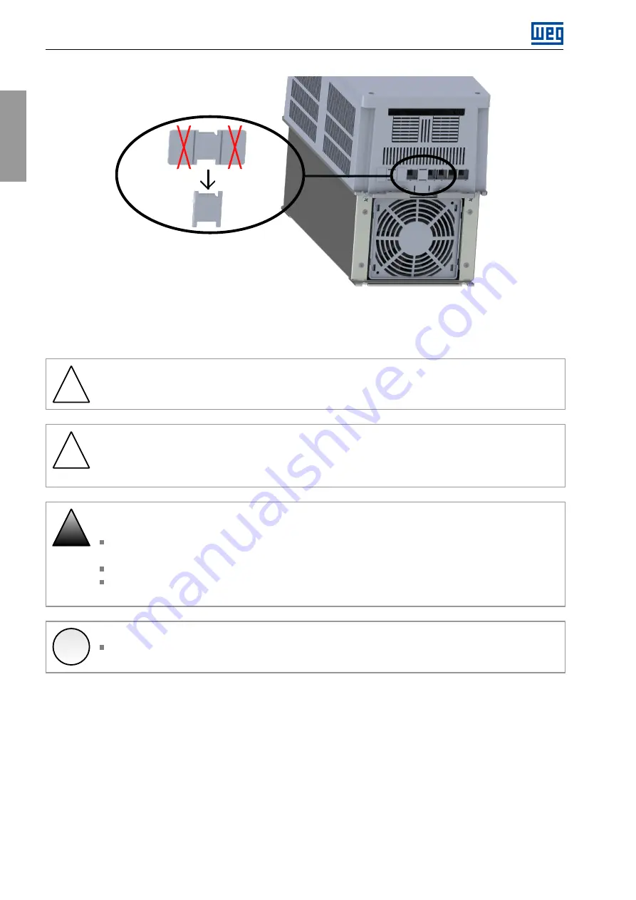
Figure 3.10:
BR terminal protection for DC link supply - frame C
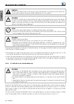
3.2.2 Power and Grounding Wiring
!
WARNING!
When power and ground connections are made with flexible cables, it is necessary to use suitable
terminals.
!
WARNING!
Sensitive equipment, such as PLCs, temperature controllers and thermocouple cables, should be at
least 0.25 meters away from the frequency inverters and cables connecting the inverter to the motor.
!
DANGER!
Wrong cable connection:
The inverter will be damaged in case the input power supply is connected to the output terminals
(U/T1, V/T2, or W/T3)
Check all the connections before powering up the inverter.
In case of replacing an existing inverter by a CFW900, check if the installation and wiring is according
to the instructions listed in this manual.
✓
NOTE!
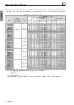
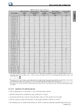
The wire gauges listed in
are orientative values. Installation conditions and the maximum
permitted voltage drop must be considered for the proper wiring sizing.
20 | CFW900
Summary of Contents for CFW900
Page 2: ......


