English
INSTALLATION AND CONNECTION
!
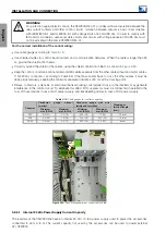
WARNING!
For protection against electric shock, the CFW900-REL-01 provides reinforced isolation between the
relay output contacts and other control circuits. Isolation between outputs is basic in accordance
with IEC61800-5-1 and UL61800-5-1 with voltage limits of 60 Vdc/25 Vac. In order to comply with
IEC and UL standards, user-accessible circuits and circuits with voltage above 60 Vdc/25 Vac must
not be activated in the same CFW900-REL-01.
For the correct installation of the control wiring:
Use cable gauge according to
.
Use shielded cables for control inputs/outputs and communication networks. When the cable is longer than 30
m, ground the shield at both ends.
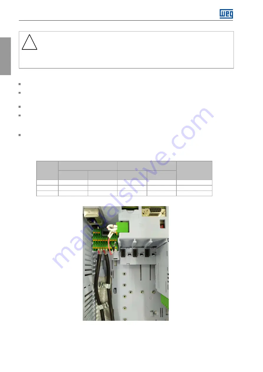
Correctly ground the shield of the cables, using the shield connection in 360°, as shown in
.
Keep the control, communication and remote HMI cables separate from the other cables (input and motor cables,
110/220 Vac control etc.) according to Table 3.9. If the those cables have to cross the other cables, it must be
done perpendicularly, keeping the minimum separation distance of 5 cm at the crossing point.
Relays, contactors, solenoids or electromechanical braking coils installed close to the inverters may generate
interference in the control circuit. To eliminate this effect, RC suppressors must be connected in parallel to the
coils of those devices in case of AC power supply, and freewheeling diodes in case of DC power supply.
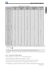
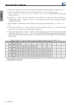
Table 3.15:
Cable gauges for control connection
Conductor
gauge
without
terminal
Conductor gauge with wire
ferrule and insulation
Conector
Minimum
mm² (AWG)
Maximum
mm² (AWG)
Minimum
mm² (AWG)
Maximum
mm² (AWG)
Stripping or
terminal length
(mm)
XC1
0.2 (24)
1.5 (16)
0.25 (23)
1.5 (16)
10 mm
XC2
0.2 (24)
1.5 (16)
0.12 (26)
0.75 (18)
10 mm
XC30
0.2 (24)
2.5 (12)
0.25 (23)
2.5 (12)
8 mm
Figure 3.23:
Connection example of control cable shield
3.2.6.1 Internal 24 Vdc Power Supply Current Capacity
The inverters of the CFW900 line have an internal 24 Vdc / 0.8 A power supply used to power the accessories
connected to slots A to G. The current capacity not used by the accessories can be used to power external
42 | CFW900
Summary of Contents for CFW900
Page 2: ......


