9-18 | MVW3000
9
Communication Networks
9-18 | MVW3000
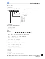
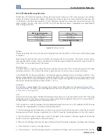
C L 1 5 CL14 CL13 CL12 CL11 CL10 CL9 CL8
MSB
LSB
CL8: 1 = Enable ramp (run/stop).
CL9: 1 = General Enable.
CL10: 1 = Forward/Reverse.
CL11: 1 = JOG.
CL12: 1 = Local/Remote.
CL13: Not used.
CL14: Not used.
CL15: 1 = Inverter "RESET".
Low-order bit: logic level of the desired action.
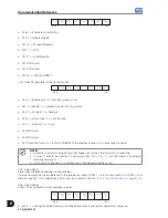
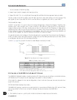
C L 7 C L 6 C L 5 C L 4 C L 3 CL2 CL1 CL0
MSB
LSB
CL0: 1 = Enable (run) / 0 = Disable by ramp (stop).
CL1: 1 = Enable / 0 = General disable (stop by inertia).
CL2: 1 = Forward / 0 = Reverse.
CL3: 1 = JOG active / 0 = JOG inactive.
CL4: 1 = Remote / 0 = Local.
CL5: Not used.
CL6: Not used.
CL7: Transition from 0 to 1 in this bit "RESETS" the inverter in case it is in some fault condition.
NOTE!
A disable command via digital input has higher priority than the Control Word enabling.
In order to enable the inverter it is necessary that CL0 = CL1 = 1, and that there is no external
disabling command.
If CL0 and CL1 are set to 0 simultaneously, than general disable occurs.
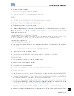
V04 (code 00804):
Serial speed reference (reading/writing variable).
It allows sending the speed reference to the inverter, as long as P0221 = 9 for Local situation, or P0222 = 9 for
Remote situation. This variable has a 13 bit resolution (refer to the
Item 9.2.1 Protocol Definitions on page 9-15
).
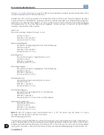
V06 (code 00806):
Status of the operation modes (reading variable).
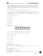
EL2
EL2
EL2
EL2
EL2
EL2
EL2 EL2
7
6
5
4
3
2
1 0
MSB
LSB
EL2.0: 1 = during the Guided Start-up Routine after a reset to the factory default/first power-up.
Summary of Contents for MVW3000 A0040 V023
Page 2: ......
Page 4: ......
Page 5: ...User s Manual Series MVW3000 Language English Document 10004823674 00 Publication Date 03 2017...
Page 6: ...Summary of Reviews Version Review Description R00 First edition...
Page 12: ...1 4 MVW3000 1 Safety Notices...
Page 58: ...6 18 MVW3000 6 Installation Connection and Energization...


