background image

MVW3000 | 9-19 

9

Communication Networks

MVW3000 | 9-19 


„

The inverter will enter this operation mode when it is powered-up for the first time or when the factory default 
parameters are loaded (P0204 = 5 or 6). In this mode only the parameters P0023, P0201, P0295, P0296, 
P0400, P0401, P0402, P0403 and P0406 will be accessible. If an attempt to access another parameter is 
done, the inverter will respond with A0125. In order to get more details, refer to the 

Item 6.3.1 Pre-power 

Checks on page 6-14

.


„

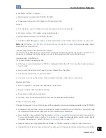
EL2.1: 1 = during the adjusting mode after changing from V/F to Vector Mode.


„

The inverter will enter this operation mode when the control mode is changed from V/F (P0202 = 0, 1 or 2) 
to Vector (P0202 = 3 or 4). In this mode only the parameters P0023, P0201, P0295, P0296, P0400, P0401, 
P0402, P0403 and P0406 will be accessible. If an attempt to access another parameter is done, the inverter 
will respond with A0125.


„

EL2.2: 1 = performing the self-tuning.


„

EL2.3: not used. 


„

EL2.4: not used.


„

EL2.5: not used.


„

EL2.6: not used.


„

EL2.7: not used.

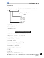
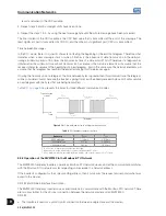
V07 (code 00807):
Status of the operation modes (reading/writing variable).


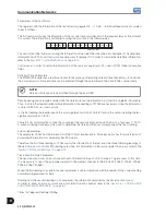
CL2 CL2 CL2 CL2 CL2  CL2 CL2 CL2


7 6 5 4 3  2 1 0

MSB

LSB


„

CL2.0: 1 - it leaves the Guided Start-up Routine after a reset to the factory default.


„

CL2.1: 1 - it leaves the adjusting mode after changing from V/F to Vector mode.


„

CL2.2: 1 - it aborts the self-tuning.


„

CL2.3: 1 - not used.


„

CL2.4: 1 - not used.


„

CL2.5: 1 - not used.


„

CL2.6: 1 - not used.


„

CL2.7: 1 - not used.

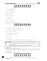
V08 (code 00808):
Motor Speed in 13 bit resolution (reading variable).
It allows reading the motor speed with a 13 bit resolution (refer to the 

Item 9.2.1 Protocol Definitions on page 

9-15

).

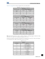
V09 (code 00809). Reading: 
b0: 1 - reversing SG (Forward/Reverse).
b1: 1 - active alarm.
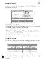
VB 12 (code 005012). Status of the Digital Outputs:
It allows controlling the status of the digital outputs that have been programmed for Serial at the parameters 
P0275 to P0280.

Summary of Contents for MVW3000 A0040 V023

Page 1: ...User s Manual Series MVW3000 Language English Document 10004823674 00 Please take this page out when unpacking the product 13941741...

Page 2: ......

Page 3: ...Motors I Automation I Energy I Transmission Distribution I Coatings Medium Voltage Frequency Inverter MVW3000 User s Manual...

Page 4: ......

Page 5: ...User s Manual Series MVW3000 Language English Document 10004823674 00 Publication Date 03 2017...

Page 6: ...Summary of Reviews Version Review Description R00 First edition...

Page 7: ...US MOTOR LINE 5 1 5 1 ABSOLUTE ENCODER WITH RSSI BOARD 5 1 5 1 1 Absolute Encoder 5 1 5 1 2 RSSI Board 5 2 5 2 FIELD EXCITATION SET DC WITH BRUSHES 5 4 6 INSTALLATION CONNECTION AND ENERGIZATION 6 1 6...

Page 8: ...rameters 9 7 9 1 6 1 Variables Read From the Inverter 9 8 9 1 6 2 Variables Written in Inverter 9 9 9 1 6 3 Error Indications 9 11 9 1 6 4 MVW3000 Variable Addressing at the Fieldbus Devices 9 12 9 2...

Page 9: ...commended in this warning have the purpose of protecting the user against dead serious injuries and considerable material damage DANGER Les proc dures concern es par cet avertissement sont destin es p...

Page 10: ...e first aid services DANGER Always disconnect the input power before touching any electrical component associated to the inverter Many components can remain charged with high voltages or remain in mov...

Page 11: ...fety condition in case of a product failure preventing accidents DANGER Ce produit n est pas con u pour tre utilis comme un l ment de s curit Des pr cautions suppl mentaires doivent tre prises afin d...

Page 12: ...1 4 MVW3000 1 Safety Notices...

Page 13: ...handling installation care troubleshooting adaption to applications and functionalities of the equipment The characteristics and recommendations contained in this manual were based on models of the s...

Page 14: ...content of this label to the purchase order In order to open the cells see the procedures described in Item 6 1 5 Unpacking on page 6 3 If the MVW3000 cells are not install on the cabinet soon store...

Page 15: ...ded N Electrolytic E Standard S Diode D 50 A A0050 3300 V V033 Al 60 Hz T6A 3300 V 033 Spanish S Water W Included S Film F Bypass B AFE A 60 A A0060 4160 V V041 Cu 50 Hz T5C 4160 V 041 Portuguese P Re...

Page 16: ...ominal speed with slip compensation Regulation 1 rpm keypad reference Sensorless Regulation 0 5 of the nominal speed Speed variation range 1 100 With Encoder using EBA EBB or EBC board Regulation 0 01...

Page 17: ...t Ethernet Kit Expans o de I Os Profibus DP 2 4 1 Available Models The MVW3000 line of medium voltage inverters offers different models classified according to their rated voltage and current levels D...

Page 18: ...00 A0060 V041 60 480 360 13 64 11 63 MVW3000 A0070 V041 70 565 425 15 92 13 57 MVW3000 A0080 V041 80 650 485 18 19 15 51 MVW3000 A0090 V041 90 730 545 20 46 17 45 MVW3000 A0100 V041 100 810 605 22 74...

Page 19: ...08 MVW3000 A0060 V069 60 810 605 22 63 19 29 MVW3000 A0070 V069 70 945 705 26 40 22 51 MVW3000 A0080 V069 80 1075 805 30 17 25 73 MVW3000 A0090 V069 90 1210 905 33 94 28 94 MVW3000 A0100 V069 100 134...

Page 20: ...1635 61 21 52 20 MVW3000 A0160 V080 160 2505 1870 69 96 59 65 13243 CFM or 22500 m h C8 MVW3000 A0180 V080 180 2815 2100 78 70 67 11 MVW3000 A0200 V080 200 3130 2335 87 45 74 57 1 The motor powers are...

Page 21: ...standard MVW3000 intended for applications on 6 6 kV motors Therefore the MVW3000 used in the general illustrations will contain 18 low voltage power cells six in series per phase Notice that the MVW...

Page 22: ...the transformer primary winding perceives multiples of six pulses in its windings The bigger the number of pulses the smaller the phase shifting angle between the secondary windings and the smaller th...

Page 23: ...3 2 POWER CELLS The power cells used on the arms of the MVW3000 are single phase low voltage inverters output voltage of 690 Vrms in a topology known as H bridge or full bridge A basic diagram of the...

Page 24: ...ircumventing the fault removing it from the series and enabling the operation to continue When that occurs control strategies will be applied so that the load remains operating Further information can...

Page 25: ...gram Figure 3 6 on page 3 6 shows the transformer input switchgear and secondary winding connected to each cell This association in series enables more voltage levels at the inverter output Locally ea...

Page 26: ...n Fiber optic Currents S and T Voltages R S and T ISOC 22 ISOC2 00 Main control Motor U V W Figure 3 6 MVW3000 simplified diagram for n power cells Therefore increasing the number of cells per phase i...

Page 27: ...3 VCC VCC 0 VCC VCC 0 VCC VCC 0 VCC Figure 3 7 Wave form of the phase voltage for a CHB of 3 cells per phase The diagram also shows the medium voltage input switchgear the low voltage auxiliary windin...

Page 28: ...control refer to Section 4 3 CONTROL RACK on page 4 6 HMI MVC4 PIC PS24 24 V 0 V MVC3 F O F O U1 U2 Wn FOI3 02 Input BT 220 V 1 or 3 Figure 3 8 Central control simplified diagram The output currents o...

Page 29: ...the cells of the invertor come from the secondary ones of the transforming one of entrance The number of cables and conductor diameter varies according to the number and current of the cells installe...

Page 30: ...in all the levels of the manufacture process The inverter parts that are not painted are zinc plated or have another suitable treatment in order to assure their resistance against corrosion Transform...

Page 31: ...electric shock with the system energized Only after closing the transformer and inverter panel doors is it possible to open the grounding system and close the input switch disconnector In case of unlo...

Page 32: ...4 7 Frame sizes available for 7200 V MVW3000 Frame size LT mm LI mm LC mm L mm H mm HV mm P mm Weight kg lb B7 3600 3000 600 7200 2063 2405 1100 6100 13448 C7 7850 17306 Table 4 8 Frame sizes availabl...

Page 33: ...ard 1 local control electronic board with fiber optic interface 2 input protection fuses 2 temperature sensors The listed items can be found in Figure 4 4 on page 4 4 and Figure 4 6 on page 4 6 Diodes...

Page 34: ...elll connection to the link is carried out by means of clamps located in the back part of the cell There are five connections per cell connecting it to the transformer three phase secondary winding te...

Page 35: ...internal use of the MVW3000 Optional Fieldbus communication and function expansion boards EBA EBB or EBC can be connected to the MVC4 control board The connections between the MVC3 board and the power...

Page 36: ...er L a Filter type 1 for applications with cable length between 200 and 500 m Shield cables Motor Inverter PE PE PE Ground loop C C C L L L b Filter type 2 for applications with cable length above 500...

Page 37: ...terlocked AC DC converter Excitation control system Crowbar MVW3000 MVC3 MVC4 RSSI Figure 5 1 General diagram of the inverter for synchronous motor 5 1 ABSOLUTE ENCODER WITH RSSI BOARD In synchronous...

Page 38: ...scillations or backlash NOTE The standard absolute encoder recommended for the MVW3000 is the Baumer MHAP 400 B5 XXXXSB14EZ D The maximum encoder cable length is 120 m Refer to the motor project to de...

Page 39: ...CLK CLK 2 Figure 5 3 RSSI Encoder connection cable NDO1 FOI3 RDA RDB N3_CHA N3_CHB N2_CHA N2_CHB NDO1 FOI3 N2 MVC3 N2 MVC3 24 V 1 Ground 2 XC1 XC2 Encoder GND 3 N3 MVC3 N3 MVC3 MVW3000 B RSSI MVW3000...

Page 40: ...o use current signals an external current transducer must be used Example of configuration of the field current reference and paremeter setting of the inverter is presented in Figure 5 6 on page 5 4 T...

Page 41: ...y isolating switches equipment for isolating the inverter power and auxiliary supplies must be planed They must cut off the inverter supplies e g during installation maintenance tasks This equipment c...

Page 42: ...e hoisting or moving the panel locate the hoisting eyes and fragile spots in the documentation that comes with the product Follow the instructions that come with the panel 6 1 3 Hoisting Make sure tha...

Page 43: ...he other avoiding pressure on fragile areas Make sure that all the panel doors be closed and locked and that the door handles be in protected position The transformer panel door must be handled with f...

Page 44: ...us avoiding mechanical instability door misalignment among other problems ATTENTION Some models of the MVW3000 are transported with some parts disassembled All disassembled parts must be properly asse...

Page 45: ...ind the panel for back access to the internal components during the product installation Notes 1 Extracted from the WEG TBG 269a standard 2 Orientative instructions Refer to the customer s specific pr...

Page 46: ...on of the Power Cells Figure 6 4 Inserted power cell Figure 6 5 Power arm insertion extraction movement trolley ATTENTION During the power arm transport they must have the locking mechanism active and...

Page 47: ...panel lift the cell up to the necessary height and couple the cart tray to the panel support Figure 6 6 on page 6 8 pictures 2 3 and 4 4 Lock the cart wheels 5 Push the cell observing the alignment w...

Page 48: ...6 1 8 Electrical and Fiber Optic Connections on the Power Cells After the power cells are inserted phases U V and W connect them to the fiber optic cables according to the labels located on the cells...

Page 49: ...B1 RX N1_UB1 TX U6 N6_UB1 RX N2_UB1 TX U7 N7_UB1 RX N3_UB1 TX U8 N8_UB1 RX N4_UB1 TX V1 N5_VA1 RX N1_VA1 TX V2 N6_VA1 RX N2_VA1 TX V3 N7_VA1 RX N3_VA1 TX V4 N8_VA1 RX N4_VA1 TX V5 N5_VB1 RX N1_VB1 TX...

Page 50: ...inverter panel to the medium voltage motor Figure 6 11 on page 6 14 must be specific for medium voltage applications and sized for the rated currents Table 6 3 Maximum current to the power cables Pow...

Page 51: ...en 37540 Cofiban Cofialt 7 kV without shield Pirelli Eprotenax 6 10 kV Ficap Fibep or EPDry 6 10 kV Use proper connectors for the power connections and the shield connections to the grounding bar Tigh...

Page 52: ...s a defect in the driving system or actuation of the protection circuit NOTE Those signals must be dry contact potential free Emergency circuits must be associated to the READY signal and never to the...

Page 53: ...be closed by the inverter otherwise the transformer and the inverter may be damaged DANGER Although the inverter commands the opening of the circuit breaker there is no guarantee of its opening In or...

Page 54: ...6 2 ELECTRICAL INSTALLATION on page 6 10 and the attached electric project How to de energize the inverter safely 6 3 1 Pre power Checks The inverter must have already been installed according to the...

Page 55: ...d the switch disconnector of the control panel auxiliary power supply is closed and check the initialization of the main control through the HMI 5 The first power up was successful the initialization...

Page 56: ...in the closing of the input switchgear F0017 Input switchgear not ready F0020 Time exceeded in the pre charge process See the description of those faults alarms in the programming manual available for...

Page 57: ...The input transformer cubicle is switched off at this moment and the INPUT ON pilot light going off indicates it ATTENTION If the input transformer cubicle does not open with the POWER OFF command th...

Page 58: ...6 18 MVW3000 6 Installation Connection and Energization...

Page 59: ...ections are made at the following terminal strips on the MVC4 control board refer to the Figure 7 1 on page 7 1 XC1A digital signals XC1B analog signals XC1C relay outputs XC1C XC1A XC2 D1 XC4 XC7 XC1...

Page 60: ...on point 16 DGND 0 V reference of the 24 Vdc supply Grounded Figure 7 2 XC1A terminal strip description active high digital inputs Terminal Strip XC1A Factory Standard Function Specifications 1 24 Vdc...

Page 61: ...nalog input 5 no function Isolated analog input signal 0 to 10 V or 0 to 20 mA 4 to 20 mA Resolution 10 bits Impedance 400 k 0 V to 10 V 500 0 to 20 mA 4 to 20 mA 12 AI5 13 AO5 Analog output 5 speed I...

Page 62: ...all them perpendicularly keeping a minimum separation distance of 5 cm 2 in at the crossing point Connect the shield as shown below The shield connection screws are located on the MVC4 board and on it...

Page 63: ...12 V 200 mA isolated internal power supply feedback for speed regulator digital speed measurement 14 bit resolution 100 kHz maximum signal frequency Available Not available Not available Buffered enc...

Page 64: ...tial analog input programmable at P0246 10 V to 10 V or 0 to 20 mA 4 to 20 mA Resolution 14 bits 0 006 of full scale range Impedance 40 k 10 V to 10 V 500 0 to 20 mA 4 to 20 mA 14 AI4 15 AGND 0 V refe...

Page 65: ...d on the left top edge until the complete insertion of the connector and the plastic spacer 5 Secure the board to the 2 metallic spacers with the 2 provided bolts 6 Plug the XC11 connector of the EBA...

Page 66: ...0 mA S3 1 RS 485 B LINE Without termination With 120 termination S3 2 RS 485 A LINE Note Both switches S3 1 and S3 2 must be adjusted for the same option Table 7 5 EBA board trimpot configurations Tri...

Page 67: ...available Analog differential input AI3 10 bits 0 to 10 V 0 to 20 mA 4 to 20 mA programmable Available Not available Available Available Not available 2 Analog outputs AO1 AO2 11 bits 0 05 of the ful...

Page 68: ...og input programmable at P243 0 to 10 V or 0 to 20 mA 4 to 20 mA Resolution 10 bits 0 1 of full scale range Impedance 400 k 0 to 10 V 500 0 to 20 mA 4 to 20 mA 14 AI3 15 AGNDI 0 V reference for analog...

Page 69: ...ke sure that all pins fit in the XC3 connector 4 Press on the EBB board near to XC3 and on the left top edge until the complete insertion of the connector and the plastic spacer 5 Secure the board to...

Page 70: ...eadjust the full scale Table 7 8 EBB board trimpot configurations Trimpot Function Factory Default Function RA5 AO1 Full scale adjustment Motor speed RA6 AO2 Full scale adjustment Motor current NOTE T...

Page 71: ...ction are described below XC21 Connector Relay Outputs and Digital Inputs XC21 Connector Function Specification 1 C DO1 Digital relay outputs Contact capacity 3 A 250 Vac 2 N 3 C DO2 4 NA 5 C DO3 6 NA...

Page 72: ...remental encoder is required The connection to the inverter is made through the XC9 connector DB9 on the EBA function expansion board or XC9 on EBB or XC10 on EBC 7 3 1 EBA EBB Boards When the EBA or...

Page 73: ...parallel with 1 k 3 Connector pinout valid for HS35B Dynapar encoder For other encoder models verify the correct connection in order to meet the required sequence XC9 connector Male DB9 red blue yell...

Page 74: ...r should have the following characteristics Power supply voltage 5 V to 15 V 2 quadrature channels 90 with complementary outputs differential Signals A A B and B Linedriver ou Push Pull output circuit...

Page 75: ...terminals XC10 22 and XC10 23 see Figure 7 19 on page 7 17 should only be used for encoder supply when the encoder power supply is not coming from the DB9 connector EBC1 board MVC4 board Figure 7 20 E...

Page 76: ...wer control cables etc If possible install the encoder cable in a metallic conduit During the commissioning it is necessary to program the control type P0202 4 Vector with Encoder in order to operate...

Page 77: ...ch ensure the energy supply to the power supplies during the specified period A filter is added to the inverter output necessary because of the characteristic of the fed loads The Short UPS feeds the...

Page 78: ...put 1 2 Iu P0652 10 V to 10 V RL 10 k Maximum load Resolution 11 bits 6 AGND 7 AO2 Analog output 2 5 modulation index P0654 10 V to 10 V RL 10 k Maximum load Resolution 11 bits 8 AGND 9 AO3 Analog out...

Page 79: ...he process as actuators In the vector mode there are two ways to implement the load sharing function in the first one the master inverter sends the slaves the torque reference signal in the second one...

Page 80: ...ts of the slave s greater than 5 added to the reference sent by the master inverter the ideal value may vary according to the application NOTE As the operation with negative torque reference is imposs...

Page 81: ...W3000 Slave n Figure 8 3 General operation scheme of the function Therefore the inverters must be parameterized as follows P0138 Rated slip the motor slip is recommended negative signal P0139 Output c...

Page 82: ...o calculate the RMS voltage that will be imposed to the motor when operating at rated frequency E g motor nameplate voltage of 4000 V and line of 4160 V Configure P0400 4160 V Configure the inverter i...

Page 83: ...erating diagram of the synchronous transfer function 8 3 CELL BYPASS The MVW3000 has the cell bypass system as optional function For this function to be available the MVW3000 power cells must have the...

Page 84: ...o exemplifies how the technique works it is possible to represent an 18 cell MVW3000 6 per phase for 18 power supplies 6 in series per phase connected in Y to the neutral point Under normal operation...

Page 85: ...ure 8 8 on page 8 7 shows the line voltage obtained in p u after the bypass of only one cell on inverters with 2 to 12 cells per phase range of possible values for the MVW3000 The situation without th...

Page 86: ...7 8 6 6 18 8 7 5 18 8 8 4 19 Table 8 2 Reduction in the line voltage in case of bypass MVW3000 21 cells U V W Reduction in the Line Voltage 7 7 7 0 7 7 6 5 7 6 6 10 7 7 5 16 6 6 6 10 7 6 5 15 7 7 4 14...

Page 87: ...that for any situation described in the tables above the order of the phases is not decisive in the reduction of the line voltage but the number of remaining cells in the system For example the situat...

Page 88: ...8 10 MVW3000 8 8 Special Functions...

Page 89: ...all it 9 1 FIELDBUS KIT 9 1 1 Installation of the Fieldbus Kit The Fieldbus kit communication board is installed directly on the MVC4 control board connected to the XC140 connector and fixed by spacer...

Page 90: ...to the Figure 9 3 on page 9 2 DEVICENET PROFIBUS DP 1 1 2 2 3 3 4 4 5 5 6 Figure 9 2 Connection to the Fieldbus board Figure 9 3 Connection to the Fieldbus board 9 1 2 Profibus DP The inverter that is...

Page 91: ...5 specification 4 Not connected 5 GND 0 V isolated from the RS 485 circuit 6 5 V 5 V isolated from the RS 485 circuit 7 Not connected 8 A Line RxD TxD negative according to the RS 485 specification 9...

Page 92: ...ed by the network configuration program Signaling The electronic board has a bicolor LED indicating the status of the Fieldbus according to the Table 9 2 on page 9 4 Table 9 2 Fieldbus status LED sign...

Page 93: ...en a network address configuration or an installation problem may be present Check the installation and the network node address Use of related Profibus DP Parameters of the MVW3000 See Item 9 1 6 Fie...

Page 94: ...ion about the element This file supplied with the product is used by the network configuration program By means of the parameter P0309 it is possible to select 2 4 or 6 input output words when P0309 i...

Page 95: ...ding to the Figure 9 9 on page 9 6 and the Table 9 5 on page 9 7 9 1 4 DeviceNet Drive Profile NOTE Refer to the DeviceNet Drive Profiles manual 9 1 5 Ethernet NOTE Refer to the Ethernet SSW 06 manual...

Page 96: ...87 57h For further information on the faults and alarms refer to the programming manual available for download on www weg net 2 Motor speed This variable is shown by using 13 bit resolution plus signa...

Page 97: ...of the digital outputs 4 Number of the parameters to be read for the option P0309 2 or 5 4I O it writes in 1 2 3 and 4 5 Number of the parameter to be changed 6 Content of the parameter to be changed...

Page 98: ...the speed reference value for the motor synchronous speed will be equal to 8191 1FFFh This value must be used only as the base speed for the calculation of the desired speed speed reference Examples...

Page 99: ...nd a new value or write in another parameter only after this time has elapsed 6 Content of the parameter to be changed selected at the position 5 Number of the parameter to be changed The format of th...

Page 100: ...he display when the HMI key is pressed E30 Inactive Fieldbus board This indication will appear when 1 P0309 is programmed different from Inactive without the existence of the respective board mounted...

Page 101: ...owing operations regarding each inverter IDENTIFICATION Network address Inverter type model Software version COMMAND General Enabling Disabling Enable Disable by ramp Run Stop Speed direction Speed re...

Page 102: ...Address 0 any inverter in the network is inquired regardless of its address Only one inverter must be connected to the network point to point in order to prevent short circuits in the interface lines...

Page 103: ...terface the connection of one master to one slave is possible point to point Data can be exchanged in a bidirectional way but not simultaneously HALF DUPLEX The logic levels follow the RS 232 EIA STAN...

Page 104: ...s 100 must be sent disregarding the decimal point Reading If 1387 disregarding the decimal point is read from P0409 them its value is 1 387 Writing in order to change V04 content to 900 rpm one must...

Page 105: ...indication reading variable Status word byte high C digo de erros byte low Where Status Word EL15 EL14 EL13 EL12 EL11 EL10 EL9 EL8 EL8 0 Enable by ramp run stop inactive 1 Enable by ramp active EL9 0...

Page 106: ...is in some fault condition NOTE A disable command via digital input has higher priority than the Control Word enabling In order to enable the inverter it is necessary that CL0 CL1 1 and that there is...

Page 107: ...another parameter is done the inverter will respond with A0125 EL2 2 1 performing the self tuning EL2 3 not used EL2 4 not used EL2 5 not used EL2 6 not used EL2 7 not used V07 code 00807 Status of t...

Page 108: ...P0220 Local Remote Selection Source P0221 Speed Reference Selection Local Situation P0222 Speed Reference Selection Remote Situation P0223 Forward Reverse Selection Local Situation P0224 Start Stop S...

Page 109: ...226 4 Selection of Fwd Rev Remote Situation by DI2 NOTE If in the inverter data reception a parity error is detected then the telegram is ignored The same will happen in cases of syntax errors Example...

Page 110: ...are necessary since the information is stored in 32 bits i e in two words In the first reading the inverter sends the most significant word bits 16 to 31 and in the second reading the less significant...

Page 111: ...B A B XC4 EBA A XC5 EBB B MVW3000 MVW3000 Cable shield A B 11 12 Figure 9 13 Connection Scheme Notes LINE TERMINATION add a line termination 120 at the ends and only at the ends of the line Therefore...

Page 112: ...widely spread and used by many manufacturers in several equipments The MVW3000 Modbus RTU communication was developed based in two documents 1 MODBUS Protocol Reference Guide Rev J MODICON June 1996 2...

Page 113: ...these registers the inverter status enabled disabled with or without error etc and the command for the inverter Start Stop Forward Reverse etc can be also accessed through the coil read write functio...

Page 114: ...ed invalid because the inverter is going to discard the already received bytes and it will assemble a new telegram with the bytes that are being transmitted Table 9 11 on page 9 26 presents the times...

Page 115: ...in the network must have an address different from the others The network master does not have an address It is necessary to know the address of the slave even when the connection is point to point Ba...

Page 116: ...l Function code 05 Broadcast supported Response time 5 to 10 ms Write Single Register Description writing in a single register of the holding type Function code 06 Broadcast supported Response time 5...

Page 117: ...65h Bit 107 107 6Bh Note all the registers parameters and basic variables are treated as holding type registers referenced starting from 40000 or 4x while the bits are referenced starting from 0000 or...

Page 118: ...re it is necessary to transmit those fields using two bytes high and low To access bits the form to represent a bit depends on the used function Both the request and response telegrams cannot be longe...

Page 119: ...e for the request and response telegrams the values are always hexadecimal and each field represents one byte Table 9 17 Telegram structure Request Master Response Slave Slave address Slave address Fu...

Page 120: ...lue byte high FFh Bit value byte high D0h Bit value byte low 00h Bit value byte low 49h CRC CDh CRC CDh CRC E5h CRC E5h For this function the slave response is an identical copy of the request sent by...

Page 121: ...gh Initial bit address byte low Initial bit address byte low Number of bits byte high Number of bits byte high Number of bits byte low Number of bits byte low Byte Count Field number of data bytes CRC...

Page 122: ...ow Number of registers byte low Byte Count Field number of data bytes CRC Data 1 high CRC Data 1 low Data 2 high Data 2 low etc CRC CRC Example Writing an acceleration time P0100 of 1 0 s and a decele...

Page 123: ...norRevision indica a vers o de firmware do inversor no formato VX XX The Read Code indicates the information categories being read and whether the objects are being accessed in a sequence or individua...

Page 124: ...ating the type of problem found Invalid function error code 1 the requested function has not been implemented for the inverter Invalid data address error code 2 the data address register or bit does n...

Page 125: ...30 Example of telegram structure Request Master Response Slave Field Value Field Value Slave address 01h Slave address 01h Function 06h Function 86h Register high 00h Error code 02h Register low 59h C...

Reviews: