9-26 | MVW3000
9
Communication Networks
9-26 | MVW3000
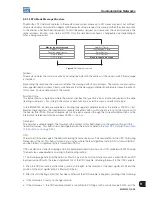
result is returned to the CRC variable.
4. Repeat steps 2 and 3 until eight shifts have been done.
5. Repeat the steps 1 to 4, by using the next message byte until the whole message have been processed.
The final content of the CRC variable is the CRC field value that is transmitted at the end of the message. The
least significant part is transmitted first (CRC-), and then the most significant part (CRC+) is transmitted.
Time between Messages:
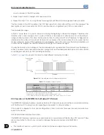
In the RTU mode, there is no specific character indicating the beginning or the end of a telegram. Therefore, what
indicates when a new message starts or when it finishes is the absence of data transmission in the network,
during a minimum period of 3.5 times the transmission time of a data word (11 bits). Therefore, if a telegram has
initiated after the minimum time without transmission has elapsed, the network elements will assume that the
received character represent the beginning of a new telegram. And in the same way, the network elements will
assume that the telegram has reached the end after lapsing this time elapses again.
If during the transmission of a telegram, the time between bytes is greater than this minimum time, the telegram
will be considered invalid, because the inverter is going to discard the already received bytes and it will assemble
a new telegram with the bytes that are being transmitted.
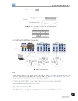
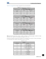
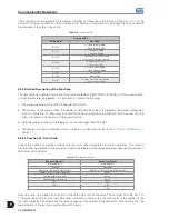
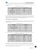
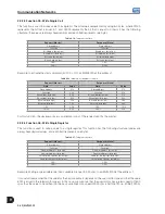
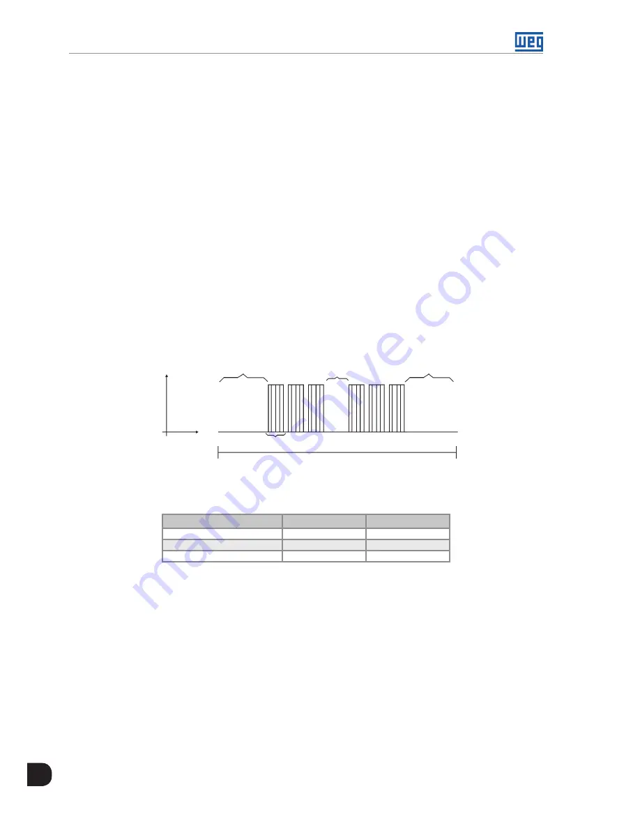
Table 9.11 on page 9-26
presents the times for three different communication rates.
Transmission
signal
Time
T
11 bits
T
3.5 x
T
between bytes
T
3.5 x
Telegram
Figure 9.16:
Time between bytes in a telegram transmission
Table 9.11:
Telegram transmission time
Baudrate
T
11 bits
T
3,5x
9600 kbits/sec
1.146 ms
4.010 ms
19200 kbits/sec
573 µs
2.005 ms
38400 kbits/sec
285 µs
1.003 ms
T 11 bits = time to transmit one word of the message.
T between bytes = time between bytes (cannot be longer than T 3.5x).
T 3.5x = minimum interval indicating the begin and the end of the message (3.5 x T 11bits).
9.3.2 Operation of the MVW3000 in the Modbus-RTU Network
The MVW3000 frequency inverters operate as Modbus-RTU network slaves, and all the communication initiates
with the Modbus-RTU network master requesting some service to a network address.
If the inverter is configured for the corresponding address, then it processes the request and responds what was
asked to the master.
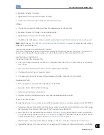
RS-232 and RS-485 Interface Description:
The MVW3000 frequency inverters use a serial interface to communicate with the Modbus-RTU network. There
are two possibilities for the physical connection between the network master and an MVW3000:
RS-232:
The interface is used for a point-to-point connection (between a single slave and the master).
Summary of Contents for MVW3000 A0040 V023
Page 2: ......
Page 4: ......
Page 5: ...User s Manual Series MVW3000 Language English Document 10004823674 00 Publication Date 03 2017...
Page 6: ...Summary of Reviews Version Review Description R00 First edition...
Page 12: ...1 4 MVW3000 1 Safety Notices...
Page 58: ...6 18 MVW3000 6 Installation Connection and Energization...


