MVW3000 | 4-1
4
MVW3000 | 4-1
Technical Data
4 TECHNICAL DATA
This chapter contains technical information on the MVW3000, cabinet details, input transformer, power cell and
control rack. It also provides information about the available output filters for the MVW3000.
4.1 MVW3000 PANEL
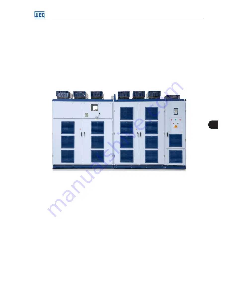
The MVW3000 is assembled as coupled panels forming four distinct compartments. In the first column of the
panel, to the left, are the input safety devices, such as fuses and the input circuit breaker/contactor (if installed).
This part also shows the input transformer temperature on the temperature display. Below the safety devices, in
a separate section, is the main medium voltage input transformer. In the central section, the inverter power cells
are installed; each of the three columns shown in
Figure 4.2 on page 4-2
represents each of the three inverter
phases: U, V and W.
Transformer and Circuit
Inverter
Control
Figure 4.1:
Closed panel of the 18-cell MVW3000 (Frame B6)
The handles of average tension that feed the cells of the invertor come from the secondary ones of the transforming
one of entrance. The number of cables and conductor diameter varies according to the number and current of
the cells installed on the MVW3000.
Each cell receives the input supply from and independent secondary winding insulated from the main transformer.
In the right panel, in the upper compartment, is the control compartment, containing the main control, user
interface, HMI, command and signalling, which are exclusively supplied by low voltage circuits.
The converter three-phase medium voltage output is located in the compartment below the control, and this
compartment can also be used to install optional output filters.
The standard panels of the models equipped with drive system and input protection feature medium voltage
fuses in order to protect the system against short circuit. The fuses must match the rated voltage of the input
medium voltage circuit.
Table 4.1 on page 4-2
presents the fuse models recommended for the standard inverters where the input and
output voltage are the same; for applications with voltage values different between input and output, the fuse
model will be informed upon request.
Summary of Contents for MVW3000 A0040 V023
Page 2: ......
Page 4: ......
Page 5: ...User s Manual Series MVW3000 Language English Document 10004823674 00 Publication Date 03 2017...
Page 6: ...Summary of Reviews Version Review Description R00 First edition...
Page 12: ...1 4 MVW3000 1 Safety Notices...
Page 58: ...6 18 MVW3000 6 Installation Connection and Energization...


