4
HMI OPERATION
Exit
13:38
F0083
LOC
0rpm
Warning
Programming Fault
F0083
!
Reset
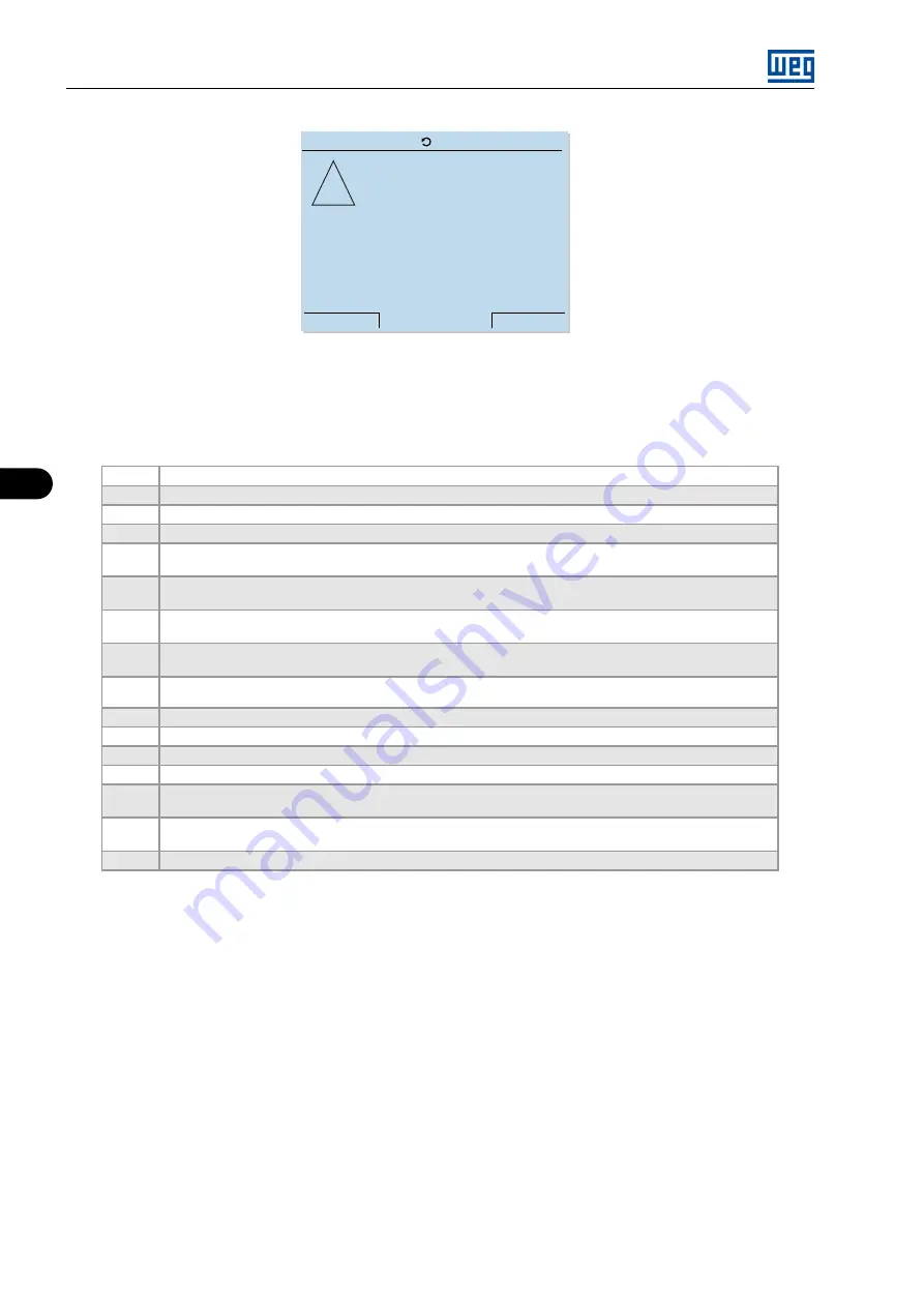
Figure 4.9:
Inverter error visualization mode
In case of incorrect inverter programming (
Table 4.5:
Incompatibility between parameters - F0083
1
Two or more parameters among P0264, P0265, P0266, P0267, P0268, P0269 and P0270 equal to 1 (LOC/REM)
2
Two or more parameters among P0265, P0266, P0267, P0268, P0269 and P0270 equal to 6 (2nd ramp)
3
P0265 equal to 8 and P0266 different from 8 or vice-versa (Forward Run / Reverse Run)
4
P0221 or P0222 equal to 8 (Multispeed) and P0266 ≠ 7 and P0267 ≠ 7 and P0268 ≠ 7
5
[P0221 = 7 and P0222 = 7] and [(P0265 ≠ 5 or P0267 ≠ 5) or (P0266 ≠ 5 or P0268 ≠ 5)]
(with reference = E.P. and without DIx = accelerate E.P. ou without DIx = decelerate E.P.)
6
[P0221 ≠ 7 or P0222 ≠ 7] and [(P0265 = 5 and P0267 = 5 or P0266 = 5 and P0268 = 5)]
(without reference = E.P. and with DIx = accelerate E.P. or with DIx = decelerate E.P.)
7
P0265 or P0267 or P0269 equal to 14 and P0266 and P0268 and P0270 different from 14 (with DIx = Start,
without DIx = Stop)
8
P0266 or P0268 or P0270 equal to 14 and P0265 and P0267 and P0269 different from 14 (without Start, with
Stop)
9
P0220 > 1 and P0224 = P0227 = 1 and without DIx = Start/Stop or DIx = Fast Stop and without DIx = General
Enable
10
P0220 = 0 and P0224 = 1 and without DIx = Start/Stop or Fast Stop and without DIx = General Enable
11
P0220 = 1 and P0227 = 1 and without DIx = Start/Stop or Fast Stop and without DIx = General Enable
12
DIx = Start and DIx = Stop, but P0224 ≠ 1 and P0227 ≠ 1
13
Two or more parameters among P0265, P0266, P0267, P0268, P0269 and P0270 equal to 15 (Man/Aut)
14
Two or more parameters among P0265, P0266, P0267, P0268, P0269 and P0270 equal to 17 (disables Flying
Start)
15
Two or more parameters among P0265, P0266, P0267, P0268, P0269 and P0270 equal to 18 (DC voltage
regulator)
16
P0264 = 1 (DI2 = LOC/REM) and P0226 = 4 (Selection of Fwd / Rev, Remote Situation by DI2)
4.5.2 Note Screen
Notes are warnings that only notify the user that some situation did not occur in the expected form; therefore they
are neither considered errors nor stored in the error log.
Notes usually occur because of configuration errors of the HMI commands (generating Modbus errors) or because
of attempts to command the inverter in not allowed situations (general enabling with the inverter in undervoltage
or error).
MVW3000 | 4-10
Summary of Contents for MVW3000 Series
Page 2: ......
Page 58: ...1 QUICK REFERENCE OF PARAMETERS AND FAULTS MVW3000 1 52...
Page 62: ...2 SAFETY INSTRUCTIONS MVW3000 2 4...
Page 192: ...6 SPECIAL FUNCTIONS MVW3000 6 4...
Page 262: ...7 DIAGNOSTICS AND TROUBLESHOOTING MVW3000 7 70...
Page 263: ......


