www.weg.net
WEG Molded Case Circuit Breakers - User’s Manual
7
Caution
When aluminum conductors are used, the application of a suitable joint
compound is recommended to reduce the possibility of terminal overheating.
Overheating can cause nuisance tripping and damage to the circuit breaker.
NOTICE
When a dual conductor terminal (Catalog No. LT3UBW400) is installed on the circuit
breaker and a single conductor is used, the conductor should be installed in the terminal
opening nearest to the circuit breaker terminal mounting conductor.
7. Connect line and load conductors and accessory leads.
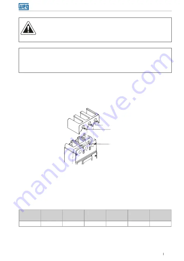
8. When step-type terminals (Cat. No. LT3UBW400) are used, terminal shields
(supplied with the terminals) must be installed on the circuit breaker (Figure 7).
Warning label supplied with the kit must be attached to the circuit breaker front
cover.
Mounting slots
Terminal cover
Dovetails
Figure 7:
terminal cover installation
9. If required, install terminal shield on circuit breaker cover with mounting screws
provided.
10. After the circuit breaker is installed, check all mounting hardware and terminal
connecting hardware for correct torque loading. Torque values for line/load
terminals are given in Table 3 and on the circuit breaker nameplate.
Terminal
cat. No.
Terminal
material
body
Screw
head type
AWG
wire
range
Metric
wire
range
Wire
type
Torque
value
lb-in (N.m)
LT1UBW400
Aluminum
Socket
250-500 (1)
120-240
Cu/Al
375 (42)
Table 3:
cover mounting hardware


