www.weg.net
14 | WECM / Emerald eZA Manual
Step 3:
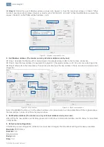
Obtain the current Modbus address, please refer Figure 14. Input the broadcast address 0, Select “Other
function”, read device ID (01-Basic Objects) or directly send “00 2B 0E 01 00 4D B7”. When the ECM Motor received the
request, the LED1 on the PCBA will flash address count.
Figure 14 - Modbus communication fail
3. Set Modbus address (The master can only set slaver address one by one):
Step 1: Establish the Modbus RTU communication, the default address is 85 for the first-time connection.
Step 2: Input the new address (for example 10) in register 7 (the register address is 00 07), and click write ( Figure 15).
Step 3: After write-in the new address, the old one is disable. Input the new address in Node, and check communication
(Figure 16).
Figure 15 - Write address
Figure 16 - Check communication
Note: If the MODBUS address is not the default address and communication can be established with the original address,
the new address can be set in the same way as above.
4. Set Modbus address (The master can only set slaver address one by one now):
After setting the new address successfully, please refer to Modbus command and address section below for more Read
/ Write details.
5. Default serial configuration:
If the Modbus serial configuration of Inverter has never been changed, then the default setting will be always available.
Baud rate: 1
9200 bits/s
Start bit:
1 bit
Data bits: 8 bits
Parity:
Even
Stop:
1 bit


