8�2
Connection
Î
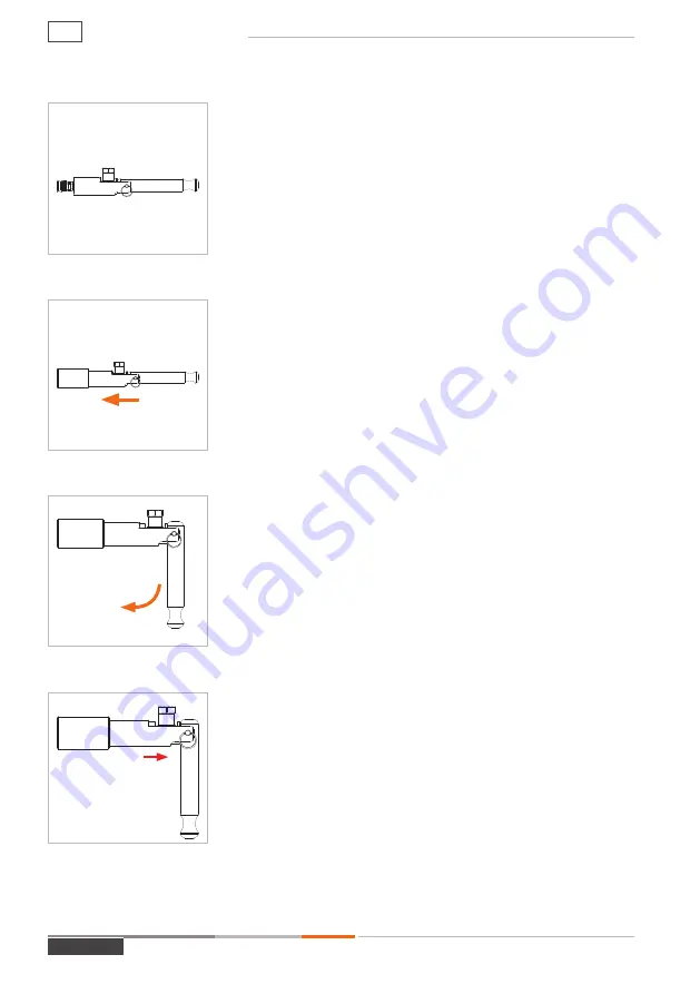
Move the clamping lever (Pos. 2) to the straight starting
position (
Figure 2
).
Î
Grip the connector by its base unit (Pos. 1) and plug it up
to the stop straight into the test piece (
Figure 3
). Doing
so will prevent any damage to the front seal caused by
any sharp edges on the test piece and ensure a correct
connection.
Attention:
Insert the connector carefully and not with force
into the test piece.
Î
Actuate the clamping lever (Pos. 2) by 90° downwards
(
Figure 4
). The connector tightens itself to the test piece
and creates a pressure-tight connection.
Attention:
Make sure that the clamping jaws on the test
piece grip correctly, that the connector is seated properly
(it must not wobble) and that the pressure-tight connec-
tion has been made. Only then is the connector connected
correctly. Otherwise the connector may spring out of place
and medium may escape.
Î
Pull lightly on the connector (red arrow
Figure 5
) in the
direction opposite that of the connection to make sure
that the connector is firmly in place.
- The connector is now connected pressure-tight to the test
piece.
Î
To start the testing procedure, apply pressure to media
inlet ‘B1’.
Figure 2
Figure 3
Figure 4
Figure 5
pull backwards
MD-10015-L51-R1.1.0-03
Page 18
Operating instructions
AE


