background image


9.


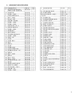
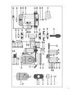
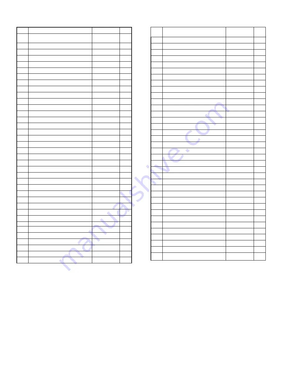
SPARE PARTS SPECIFICATION 


  DENOMINATION 

ITEM №


PCS. 

ELECTRIC DRIVE MOTOR 


MR90C/2 INCL. CAPACITOR 

P2019.401 

1A  CAPACITOR 

P2019.402 

SCREW 

 M6X10 

P2019.103 

DRIVE MOTOR PLATE 

P2019.104 

BOLT 

 M8X20 

P2019.105 

PULLEY 

 Ø97 

P2019.206 

WASHER 

 Ø6XØ26 

P2019.107 

SCREW 

 M6X16 

P2019.108 

SCREW 

 M4X20 

P2019.109 

CONTACTOR 

 LT1-D 

P2019.110 

10  CONTACTOR PLATE 

P2019.111 

11  SCREW 

 M5X12 

P2019.112 

12  SEPORATER 

P2019.213 

13  BACK HANDLE 

P2019.114 

14  HYDROPLANING PLATE 

P2019.115 

15  SCREW 

 M6X20 

P2019.116 

14 

16  KNEE 

 3/8" 

P2019.117 

17  FILTER 

P2019.118 

18  FILTER MESH 

P2019.119 

19  SEAL 

P2019.120 

20  NIPPLE 

P2019.121 

21  CLAMP 

P2019.122 

22  RUBBER HOSE 

P2019.123 

23  QUICK CONNECTION 

P2019.124 

24  SPHERICAL VALVE 

 3/8" 

P2019.125 

25  NIPPLE 

P2019.126 

26  BOLT 

 M6X30 

P2019.127 

27  NIPPLE 

P2019.126 

28  SEAL 

 10X3 

P2019.128 

29  BOLT 

 M8X20 

P2019.129 

30  SPHERICAL VALVE 

 3/8" 

P2019.125 

31  BLEND 

P2019.130 

32  HINGED WATER SUPPLY 

P2019.131 

33 

KNOB “UP 

DOWN”


P2019.132 

34  STOP SCREW 

 M5X10 

P2019.133 

35  WASHER 

 Ø8 

P2019.134 

36  SCREW 

 M6X20 

P2019.116 


DENOMINATION 

ITEM №


PCS. 

37  PIN BEARING BLOCK 

P2019.135 

38  PLATE SPRING 

P2019.136 

38A  WIDE WASHER 

 Ø8X20 

P2019. 134A 

 39  PIN 

P2019.137 

40  RUBBER SEAL 

P2019.140 

41  SPINDLE MOOVING BLOCK 

P2019.138 

42  SCREW 

 M6X20 

P2019.116 

43  SPINDLE HOUSING 

P2019.139 

44  BELT 

 630X20X1.7 

P2019.341 

45  FRONT HANDLE 

P2019.142 

46  WATER PROTECTION 

P2019.143 

47  WATER PROTECTION HOLDER 

P2019.144 

48  COVER 

P2019.145 

49  SCREW 

 M4X8 

P2019.146 

50  SPINDEL COVER 

P2019.147 

51  SPINDEL NUT 

P2019.148 

52  BEARING 

 7206C 

P2019.149 

53  PLATE SPRING 

P2019.136 

54  STOP BUTTON 

P2019.150 

55  START BUTTON 

P2019.151 

56  PROTECTION COVER 

P2019.152 

57  LEFT OUTER BLOCK 

P2019.153 

58  LEFT INNER BLOCK 

P2019.154 

59  LABYRINTH NUT 

P2019.155 

60  LABYRINTH 

P2019.156 

61  SPINDLE 

P2019.157 

62  POWER SUPPLY CORD 

P2019.158 

63  SATELIT 

P2019.259 

64  COVER 

P2019.160 

65  SCREW 

 M4X12 DECORATION  P2019.161 

66  BODY 

P2019.262 

67  RIGHT OUTER BLOCK 

P2019.163 

68  RIGHT INNER BLOCK 

P2019.164 

69  WASHER 

 Ø10 

P2019.165 

70  BOLT 

 M10X30 /50/ 

P2019.166 

71  SET OF WRENCHES 

P2019.167 


Summary of Contents for ROCK DOG ROUTER

Page 1: ... 18 Frame 1 Piece Aluminum housing Power 2 4 HP Supply tensions 220V 60Hz single phase Thermal overload safety cut out Base Aquaplaning system Machine length 22 width 13 7 height 15 Power cord 20 feet 12 gauge AWF w ground Machine weight 77 lbs Packed wooden case 23 x 15 x 19 Shipping weight 100lbs ROCK DOG ROUTER ...

Page 2: ...e from rain and store the machine in the dry place Extreme caution and care must be observed when using any extension cord connected to the machine s electrical cord If an extension cord must be used make sure that it is of adequate wire size to carry the required voltage current safety Extension cord wire diameter must be proportionally larger than the machine s electrical cord according to its l...

Page 3: ...which must be equipped with a shut off and connect the other end to the male quick connect hose fitting which comes with the machine The water shut off allows you to turn off the water flow when the unit is temporarily not in use and during tool replacement The water supply must deliver a minimum pressure of 60 PSI and flow capacity of least 4 Gallons per minute 15 liters min It s recommended to u...

Page 4: ...pening too much could stop the aquaplaning system to work properly and make scratches on the slab While working the water stream should follow the clockwise rotation of the tool Start machine and adjust the tool Rotate the knob in a clockwise direction to raise and counterclockwise to lower the tool ONLY adjust the tool by turning spindle to avoid damaging the adjusting system The operator should ...

Page 5: ...NOB UP DOWN P2019 132 1 34 STOP SCREW M5X10 P2019 133 1 35 WASHER Ø8 P2019 134 1 36 SCREW M6X20 P2019 116 2 DENOMINATION ITEM PCS 37 PIN BEARING BLOCK P2019 135 1 38 PLATE SPRING P2019 136 2 38A WIDE WASHER Ø8X20 P2019 134A 1 39 PIN P2019 137 1 40 RUBBER SEAL P2019 140 1 41 SPINDLE MOOVING BLOCK P2019 138 1 42 SCREW M6X20 P2019 116 2 43 SPINDLE HOUSING P2019 139 1 44 BELT 630X20X1 7 P2019 341 1 45...

Page 6: ...5 ...

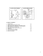
Page 7: ... INSTRUCTIONS FOR CONNECTING THE POWER SUPPLY p 1 4 INSTRUCTIONS FOR CONNECTING THE WATER SUPPLY p 1 5 INSTRUCTIONS FOR MACHINE USE p 2 6 PREPARING THE MACHINE FOR OPERATION p 2 7 OPERATION p 3 8 MAINTENANCE AND CLEANING p 3 9 SPARE PARTS SPECIFICATION p 4 10 TABLE OF CONTENTS p 6 ...

Reviews: