background image


于千钧

“1005098300 - Operation_and_Maintenance_Manual_for_PowerKit_16M33_Series_Gas_Engine, A”

林世龙

许太法

宋安泽

20200425

于千钧

张安勇/Zhang Anyong

王巧荣

Summary of Contents for BAUDOUIN PowerKit 16M33 Series

Page 1: ...1 于千钧 1005098300 Operation_and_Maintenance_Manual_for_PowerKit_16M33_Series_Gas_Engine A 林世龙 许太法 宋安泽 20200425 于千钧 张安勇 Zhang Anyong 王巧荣 ...

Page 2: ...ration and Maintenance Manual for PowerKit 16M33 Series Gas Engine OMMBV2003 于千钧 1005098300 Operation_and_Maintenance_Manual_for_PowerKit_16M33_Series_Gas_Engin 林世龙 许太法 宋安泽 20200425 于千钧 张安勇 Zhang Anyong 王巧荣 ...

Page 3: ...serves the right to modify these specifications without notice Safety The Safety section of this manual covers basic safety precautions and shows warnings and potentially hazardous situations This Manual must be read in full before operating your PowerKit in order to operate and maintain the engine safely Maintenance Spare Parts Maintenance should be carried out at the appropriate intervals as sho...

Page 4: ...ation 33 3 1 Engine Lifting 34 3 2 Engine Mounting 37 3 3 Accessories 38 3 4 Air Intake System 39 3 5 Exhaust System 39 3 6 Cooling System 39 3 7 Lubrication System 40 3 8 Gas Supply System 40 3 9 Engine Electronic System 42 3 10 Engine Electronic Controlling System 43 3 11 Gen Set Installation Recommendation 48 4 Operation 49 4 1 Preparations before Start 50 4 2 Starting Up 52 4 3 Operation of th...

Page 5: ...endation 90 6 2 Lubricant Recommendation 91 6 3 Fuel Recommendation 93 6 4 Special Tools Recommendation 94 6 5 Common Faults and Troubleshooting 97 6 6 Maintenance Log 137 Index 140 于千钧 1005098300 Operation_and_Maintenance_Manual_for_PowerKit_16M33_Series_Gas_Engin 林世龙 许太法 宋安泽 20200425 于千钧 张安勇 Zhang Anyong 王巧荣 ...

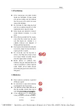
Page 6: ...dents can be prevented by following basic safety precautions recognizing hazardous situations and acting accordingly but these safety instructions alone are not sufficient to avoid every hazard Baudouin cannot anticipate or identify every possible hazard in your operating environment Persons operating or maintaining the engine must be able to recognize hazardous situations and they must have the n...

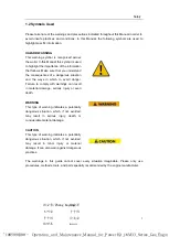
Page 7: ...comply with warnings can result in material damage serious injury or even death WARNING This type of warning indicates a potentially dangerous situation which if not avoided may result in serious injury death or considerable material damage CAUTION This type of warning indicates a potentially dangerous situation which if not avoided may result in minor injury or material damage It can also warn ag...

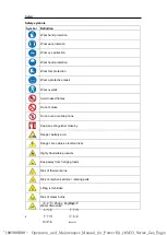
Page 8: ...o not use a mobile phone Keep an extinguisher close by Danger battery acid Danger live cables electrical risks Highly flammable products Keep away from hanging loads Risk of thermal burns Risk of mechanical drive rotating parts Lifting is forbidden Risk of steam burns Water drain valve 于千钧 1005098300 Operation_and_Maintenance_Manual_for_PowerKit_16M33_Series_Gas_Engin 林世龙 许太法 宋安泽 20200425 于千钧 张安勇 ...

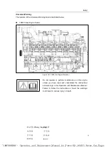
Page 9: ...e or perform maintenance on this engine unless you have read and understand the instructions and warnings in this Operation and Maintenance Manual Failure to follow the instructions or heed the warnings could result in serious injury or death 于千钧 1005098300 Operation_and_Maintenance_Manual_for_PowerKit_16M33_Series_Gas_Engin 林世龙 许太法 宋安泽 20200425 于千钧 张安勇 Zhang Anyong 王巧荣 ...

Page 10: ...afety glasses or a face shield An eye rinsing solution must be kept close at hand Do not spill oil or other fluids on the ground when repairing the engine In the event of an accidental spillage of hydrocarbon or other fluid take all the necessary measures to section off the area clean up and protect people and the environment The handling storage and recycling of hydrocarbons ethylene glycol and o...

Page 11: ...proximity to engine genset or system Do not smoke near the fuel tank or while in the filling area Ensure there are no open flames or sparks Always stop the engine before refuelling Mobile phones in particular their batteries may give off sparks that could cause an explosion in certain high risk areas Switch off all mobile phones when filling the gas tank or while in the filling area 1 6 Batteries ...

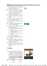
Page 12: ...affected part with plenty of water Apply bicarbonate of soda or lime to neutralise the acid Rinse your eyes for 10 to 15 minutes See a doctor immediately In the event of ingestion see a doctor immediately Make sure the batteries are clean and fitted with the recommended covers cables and connections Electric wiring must be kept in good condition properly positioned and attached 1 7 Welding Do not ...

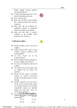
Page 13: ...tached All wires should be of the recommended size Wires and cables must be protected by a fuse or calibrated circuit breaker Do not short circuit fuses and or circuit breakers The electrical circuit of the engine must be isolated from the engine and generator Ensure that the engine is grounded correctly to prevent uncontrolled electrical circuit paths which can cause damage Insulation problems ca...

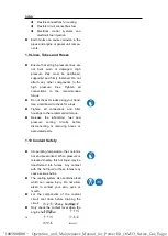
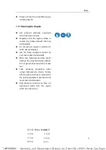
Page 14: ...ions and filter housings to the recommended torque Release the lubrication fuel and pressure cooling circuits before disconnecting or removing hoses or associated parts 1 10 Coolant Safety At operating temperature the coolant is hot and pressurized When pressure is released sharply this hot liquid may be transformed into fumes Any contact with this hot liquid or these fumes may cause serious burns...

Page 15: ... local codes and standards Make sure high pressure water cannot damage the equipment being washed Do not get electrical equipment or seals wet Take necessary precautions when using a high pressure cleaner Comply with the safety instructions indicated for the cleaning equipment used as well as local codes and standards High pressure cleaning can blow out high speed debris from the engine which can ...

Page 16: ...stood Clear the engine of any flammable materials such as fuel oil or debris Do not smoke near the engine or where flammable materials are stored Exhaust shields if equipped must be fitted correctly Do not expose the engine or components to flames Do not touch hot parts of an engine in operation or which has just been stopped Ensure the starter battery insulation switch is in open position Switch ...

Page 17: ...tor terminals or the batteries as this could damage the electrical system Never bypass or disable the automatic shutoff circuit these are provided to help prevent injury and engine damage Engine exhaust could be harmful to your health therefore always start and operate the engine in a well ventilated area If in an enclosed area ensure the engine exhaust is vented properly to the outside 1 12 3 Sto...

Page 18: ...ower is allowed No overload ability PRP Unlimited Prime Rated Power Annual running time is unlimited The average load rate is no more than 70 during a range of 24 hours Maximum time range with overload 10 within 12h is 1 hour 于千钧 1005098300 Operation_and_Maintenance_Manual_for_PowerKit_16M33_Series_Gas_Engin 林世龙 许太法 宋安泽 20200425 于千钧 张安勇 Zhang Anyong 王巧荣 ...

Page 19: ...e number 2 4 6 as the different power lever for the models choose 2 as the lowest power and increase the power with the order of the number 1 3 5 7 as the alternate power code and will be used according to market demands For the single speed engines that without emission can only be used for PRP or ESP Power code for 50Hz correspond Standby Power kVA of generating set Power code for 60Hz correspon...

Page 20: ...EPA Tier 3 EU Stage ⅢA B China stage Ⅲ 4 U S EPA Tier 4 India CPCB Ⅳ EU Stage Ⅳ China stage Ⅳ 5 EU stageⅤ 6 EU stage Ⅵ Note1 New product model should be compiled on the basis of the most stringent Emission legislation Note2 Current model name can still be used when applying for another emission certification with existing product 2 2 1 7 Fuel Code The fuel code of diesel oil is indicated by D natu...

Page 21: ... 2 Engine Plate 16M33 Series Gas engine Figure 2 2 2A 16M33 Gas Engine Plate Position 于千钧 1005098300 Operation_and_Maintenance_Manual_for_PowerKit_16M33_Series_Gas_Engin 林世龙 许太法 宋安泽 20200425 于千钧 张安勇 Zhang Anyong 王巧荣 ...

Page 22: ...l Oil Filter 8 Oil Cooler 9 Oil Filter 10 Low Temperature Water Pump 11 Alternator 12 Water Thermostat 13 Air and Gas Intake Manifold High Temperature 14 Water Pump 15 Water Draining Valve 16 Oil Pan 17 Oil Filling Cap 18 Pre lubricating Pump 19 Oil Gas Separator 20 Flywheel Housing 21 Electronic Throttle 于千钧 1005098300 Operation_and_Maintenance_Manual_for_PowerKit_16M33_Series_Gas_Engin 林世龙 许太法 宋...

Page 23: ...6 1 Coolant Recommendation The high temperature coolant pump is located at the engine s front side See item 2 of the above picture b Low temperature cooling circuit The low temperature cooling circuit cools the charged air and gas 2 4 1 High Temperature Cooling Circuits for 16M33 Series Gas Engine Overall Layout Figure 2 4 1 Overall Layout of high temp cooling circuits 1 Radiator 2 Water pump 3 Oi...

Page 24: ... Layout Figure 2 4 2 Overall Layout of low temp cooling circuits 1 Radiator 2 Low temp Water pump 3 Cooled Water Line 4 Intercooler 5 Water Back to Radiator 于千钧 1005098300 Operation_and_Maintenance_Manual_for_PowerKit_16M33_Series_Gas_Engin 林世龙 许太法 宋安泽 20200425 于千钧 张安勇 Zhang Anyong 王巧荣 ...

Page 25: ...ridges are equipped with a by pass valve allowing the continuity of the engine lubrication even in case of a sudden clogging b Centrifugal oil filter s Centrifugal oil filters of 16M33 gas engine are installed in bypass on both side of the engine 1 Oil Sump 10a Conrod bearings 2 Suction strainer 7b Camshaft bearings 3 Oil pump 7c Cylinder head lubri cating oil pipe 4a Centrifuge filter 4b Oil Filt...

Page 26: ... by turbocharger and then cooled by intercooler The throttle controls the amount of gas air mixture coming into the intake manifold the combustion chambers Overall Layout of Gas Supply System Gas line Air line Line of mixture of gas and air 1 Gas Filter 2 Shut Off Valve 3 Pressure Reducer 4 Gas Metering Valve 5 Air Line 6 Gas Line 7 Mixer 8 Turbocharger 9 Intercooler 10 Throttle 11 Intake Manifold...

Page 27: ...fety protection switch on the gas pipeline Technical parameters Max working pressure 360mbar Working temperature 15 60 Working voltage 24V DC Pressure Reducer Function description Reduce and regulate the compressed gas pressure to required level Technical parameters Inlet pressure 1000mbar Outlet pressure 50mbar 130mbar Working temperature 15 70 Figure2 6 3 Pressure Reducer 于千钧 1005098300 Operatio...

Page 28: ...ion are fully mixed to make the combustion more fully and soft effectively reducing the NOx emission and exhaust temperature Figure2 6 4 Gas and Air Mixer 于千钧 1005098300 Operation_and_Maintenance_Manual_for_PowerKit_16M33_Series_Gas_Engin 林世龙 许太法 宋安泽 20200425 于千钧 张安勇 Zhang Anyong 王巧荣 ...

Page 29: ...ne parameters Technical parameters Working voltage 24V Working environment 40 100 40 85 with EID Figure2 7 1 ECU Engine Control Unit To prevent any damage to ECU it is forbidden to carry out hot plugging operation on ECU Inlet temperature pressure sensor T MAP Function description T MAP sensor integrates pressure and temperature measurement Engine control unit ECU uses sensor signals to calculate ...

Page 30: ...ing temperature measuring terminal 40 150 Rated working voltage 5 0 25 V Installation gap shall be 0 2mm 2mm Figure2 7 3 Camshaft signal sensor Water temperature sensor Function description Water temperature sensor is mainly used to measure cooling water temperature ECU may regulate idle speed and ignition advance angle in different water temperatures according to ECU stored data Technical paramet...

Page 31: ...ttle is mainly used for controlling mixture flow engine idling and maximum revolving speed ECU controls the action of throttle and its working stroke is limited to 10 90 opening of butterfly valve by ECU Failure of electronic throttle or bad contact of connectors will lead to unstable revolving speed unable to start inhibited acceleration unable to acceleration and other failures Use multi meter t...

Page 32: ...sed to transmit high pressure spot generated by ignition coil to sparking plug so as to generate electric spark for ignition of combustible mixture Figure2 7 9 Ignition cable Spark plug Function description Sparking plug is used to receive high voltage generated by ignition coil generate electric spark and ignite flammable gas This engine uses double platinum sparking plug Figure2 7 10 Spark plug ...

Page 33: ...stallation and operation instructions defined by Baudouin will void the warranty Notice After the gas engine is unpacked firstly the user shall check the gas engine and its accessories as per the delivery packing list and check the engine appearance for damage and loose connections before handling the following tasks Check all parts to be self provided are properly fitted Do not start the gas engi...

Page 34: ...strated Avoid any contact between the chains and the engine parts The lifting hook and the engine lifting eye should be connected tightly There is the risk of death or injury due to heavy suspended loads Figure 3 1 2 Lifting of the engine 3 1 3 Lifting Brackets Note Please refer to the Gen Set Manual when lifting the generator Use all the four lifting brackets fitted on the gas engine to lift Duri...

Page 35: ...are illustrated as following Figure 3 1 3 A Right lifting eyes face to the flywheel Figure 3 1 3 B Left lifting eyes face to the flywheel 于千钧 1005098300 Operation_and_Maintenance_Manual_for_PowerKit_16M33_Series_Gas_Engin 林世龙 许太法 宋安泽 20200425 于千钧 张安勇 Zhang Anyong 王巧荣 ...

Page 36: ...ance between left lifting brackets and right lifting brackets Figure 3 1 3 D Dimensions of lifting bracket 于千钧 1005098300 Operation_and_Maintenance_Manual_for_PowerKit_16M33_Series_Gas_Engin 林世龙 许太法 宋安泽 20200425 于千钧 张安勇 Zhang Anyong 王巧荣 ...

Page 37: ...to reduce vibration from the engine to its chassis For the engine s installation angle The front rear orientation limitation is 10 The left right orientation limitation is 22 5 The mounting brackets of 16M33 series gas engine are illustrated as following Figure 3 2 A Right brackets 于千钧 1005098300 Operation_and_Maintenance_Manual_for_PowerKit_16M33_Series_Gas_Engin 林世龙 许太法 宋安泽 20200425 于千钧 张安勇 Zhan...

Page 38: ... pipes As the figure 3 3 the O ring should be arranged in the flange before it was connected to the radiator outlet pipe When you connect the pipes such as in air system and cooling system be sure to use the high quality rubber pipe to avoid the unnecessary leakage Figure 3 3 Coolant pump inlet port 于千钧 1005098300 Operation_and_Maintenance_Manual_for_PowerKit_16M33_Series_Gas_Engin 林世龙 许太法 宋安泽 202...

Page 39: ...elative movement between components and dimensional change due to thermal load can exert excessive stress Avoid the exhaust pipe having sharp turns The bend radius of the pipe should be big as much as possible and sharp corner is not allowed When the exhaust pipe is close to the intake pipe rubber parts plastic parts fuel tanks etc an insulation board must be added in the middle and the distance s...

Page 40: ...ure circuit 80mm outlet of high temperature circuit 84mm inlet of low temperature circuit and 60mm outlet of low temperature circuit The minimum distance from fan front end to radiator is 150mm The coolant capacity of the engine W O radiator is approx 100L 3 7 Lubrication System Users must follow the requirements in 6 2 Lubricant Recommendation To get a good performance of the engine lubricant sys...

Page 41: ... proper sealing and high reliability The high pressure pipeline shall be provided with an upstream protection device to cut off the gas when the engine is stopped or gas is leaking Test connection points with leakage detecting liquid under the rated gas working pressure and no bubble detected within 1 minute Alternatively check with a gas detector with at least 25ppm measurement accuracy 3 8 2 Gas...

Page 42: ...protective caps Control circuit resistance recommended Resistance from battery to starter 50c terminal plus resistance from starter yoke to battery terminal 500Ω Main circuit wiring resistance recommended Resistance from battery to starter 30 terminal plus resistance from starter yoke to battery terminal 2mΩ 20 Battery and main circuit wiring resistance range recommended 8mΩ 20 battery 100 charged...

Page 43: ...Figure 3 10 1 A Wire for ECU power key switch wire ECU pin No J1 12 Connect the wire with the battery with a key switch Functional description The switch is ECU power switch When the switch is ON ECU will in working condition When the switch is OFF the engine will be stopped Any interference on this switch from other electrical devices should be avoided When the key switch is turned on the engine ...

Page 44: ...ller immediately disconnects the switch and the engine stops The run stop switch can be connected to a mechanical manual switch or a passive contact switch control It is forbidden to share the same relay with other device switches Figure 3 10 1 C Wire for Run Stop switch Idle rated switch wire Pin No J1 59 Functional description When the switch is on the speed rises to the rated speed When the swi...

Page 45: ...will remain at the same speed as before the disconnection The wire cross sectional area is 0 75mm 2 This switch is manually parallel or connected to the grid If there is no parallel or grid connection no connection is required The customer needs to prepare the manual switch by himself Figure 3 10 1 E Wire for Manual Speed adjustment switch Speed Bias Pin No J1 57 J1 45 J1 69 shield Functional desc...

Page 46: ... the transmitted message information is guaranteed to be error free No connection to the network or parallel requirements no need to connect this interface Figure 3 10 1 F Wire for Speed Bias switch Generator breaker switch wire Pin No J1 82 Functional description It is applied to the engine that needs to be connected with the grid When the grid starts running the signal switch needs to be on When...

Page 47: ...nating resistor is integrated in the ECU If the CAN cable is shielded make sure that the shield is grounded at one end and the other end is left open Do not ground the two ends The ECU is affected by the interference caused by the current caused by the ground pressure difference being coupled to the CAN line Figure 3 10 1 H DB9 type connector 于千钧 1005098300 Operation_and_Maintenance_Manual_for_Pow...

Page 48: ...oncrete foundation should be at least 200mm thick When installing the vibration absorbers are evenly placed under the unit chassis The unit levelness is recommended to be measured with the level gauge When building a room for gen set the proper device for lifting should be embedded in the roof for future maintenance There should be enough maintenance and inspection space around your gen set The ro...

Page 49: ...prevent from over speed risks Check the cleanliness of circuits Check for free circulation of gases in exhaust ducts Check the natural gas supply Check coolant level and fill if necessary Check oil level and fill if necessary Check air filter clogging indicator Pre lubricate before engine start up after an engine has been stopped longer than 24h for a shorter period pre lubrication is unnecessary ...

Page 50: ...r or heat exchanger and bleed the air from the cooling circulation system When opening the filler cap with the pressure relief valve and exhaust button press the exhaust button first if the engine is still hot It is prohibited to add a large amount of coolant when the engine is still hot for it will cause damage to the parts due to sudden temperature change Start the engine keep adding coolant unt...

Page 51: ... installed in site please make sure must remove all long adjustment bolts of bellows before starting the genset 于千钧 1005098300 Operation_and_Maintenance_Manual_for_PowerKit_16M33_Series_Gas_Engin 林世龙 许太法 宋安泽 20200425 于千钧 张安勇 Zhang Anyong 王巧荣 ...

Page 52: ...s bulbs and but tons once by pressing the touch button 10 on the control panel Turn the key to position START to start the engine and then release the key The key will automatically return to position 1 Figure 4 2 A Pre lubricating oil pump Figure 4 2 B Switch NOTE At the start of engine if the engine fails to start within 10s immediately release the button and wait for 1min before retry If the en...

Page 53: ... after intercooler 45 55 º C Check the exhaust color to estimate the performance of the combustion and the load of the engine In the case of serious black or white smoke stop and check the engine Check the engine for presence of water gas and oil leakages Figure 4 3 Smoke Most of the failures will have early warning Listen and observe to discover the performance sound and appearance changes of gas...

Page 54: ...ge If the engine is not going to be operated for a long time and under very low temperatures the battery should be removed and stored in a warmer room Shut down of the engine When shutting down the engine in a cold climate unload the engine first and then run the engine at idling speed for 1 to 2 minutes And then stop the engine after the water and oil temperatures decrease The coolant with antifr...

Page 55: ...When the engine shuts down suddenly the turbocharger temperature will increase greatly and cause the bearing or the oil seal to fail Turn the key switch to position 0 or press the stop button to stop running of engine till the engine stops rotation or the speed indicator on the instrument panel points zero For the engines that don t use anti freeze in the engine coolant drain the coolant after shu...

Page 56: ...st for several times the subsequent fault codes will be shown one by one When the first fault code is repeated it indicates that all the fault codes have been read Check the List of fault codes to find the explanation corresponding to each fault code and you can determine the current fault Please check the code sheet at 6 5 Common Faults and Troubleshooting 于千钧 1005098300 Operation_and_Maintenance...

Page 57: ... alignment The tightness of the entire engine unit on the frame The tightness of the couplings and all elements transmitting power The isolation and condition of electrical equipment The condition and tightness of electrical connections Control of gas lubricating oil and coolant levels Operation of the alarm safety devices Replacement of gas lubricating oil and air filters 于千钧 1005098300 Operation...

Page 58: ...gas pressure in the pipeline Oil level The fan Lube grease quantity for fan pulley bearing and fan belt tensioner bearing о Exhaust gas colour The sound The speed and vibration of gas engine Presence of water gas and oil leakages The air cleaner service indicator if equipped Gas filter Belt Simple overall check Hose clamps Hoses and pipes 于千钧 1005098300 Operation_and_Maintenance_Manual_for_PowerKi...

Page 59: ... Δ Condensing draining pipes if equipped Δ Defaults recorded in ECU Belt and tensioning Centrifugal oil filter cartridge s Breather filter cartridge Δ The engine and generator connection The intercooler air and water side Δ Spark Plug Δ Intercooler Δ Radiator and cooling system Δ Oil cooler s Δ The rocker arm and cross bar clearance о 于千钧 1005098300 Operation_and_Maintenance_Manual_for_PowerKit_16...

Page 60: ... Conditions and tightness of electrical connections State and tightness of alternator State and tightness of starter Tightness of couplings and all elements transmitting power Turbocharger axial and radial clearances Turbocharger air intake side and air pipes Δ Turbocharger The elastic support of engine Thermostatic valves LT circuit Oil pressure sensor Hoses Coolant temperature sensor Coolant 于千钧...

Page 61: ...00 Month 12 12 12 12 24 Coolant pump Gas shutoff valve Gas reducer Gas pipes Overhaul Top 1 Overhaul Structure 2 Overhaul Major 3 1 Reference to Chapter 5 3 2 2 Overhaul Top 2 Reference to Chapter 5 3 2 3 Overhaul In Structure 3 Reference to Chapter 5 3 2 4 Overhaul Major 于千钧 1005098300 Operation_and_Maintenance_Manual_for_PowerKit_16M33_Series_Gas_Engin 林世龙 许太法 宋安泽 20200425 于千钧 张安勇 Zhang Anyong 王...

Page 62: ...evel is appropriate Figure 5 3 1 A Filling Coolant NOTE Do not let coolant drip or leak out onto the ground or into the bodies of water while filling Otherwise the environment will be damaged The engine s cooling system is to be filled with a mixture of coolant glycol and special additives Never add the normal plain water only Specific requirement about coolant see the Part Annexes Coolant can onl...

Page 63: ...e 5 3 1 E on the coolant pumps to release air in the high temperature circle when coolant flow out of the plug screw hole tighten the plug screw with a torque 30N m Figure 5 3 1 C For the low temperature circle release this screw plug on the pipe connected with the intercooler to release air in the low temperature circle when the coolant flow out of the screw plug hole tighten the plug with a torq...

Page 64: ...k coolant before the next commissioning with engine cold Add coolant if necessary Repeat this procedure until coolant no longer is added Figure 5 3 1 E Check the gas NOTE Never bring flames near gas tank because it is highly flammable and dangerous Check gas pressure and leakages If the gas is not enough add gas meeting the standards Figure 5 3 1 F 于千钧 1005098300 Operation_and_Maintenance_Manual_f...

Page 65: ...lint free cloth Reinsert oil dipstick until fully seated Figure 5 3 1 G Pull out oil dipstick again and check oil level The oil level should be between both of the marks on the dipstick and should never drop below the lower mark Figure 5 3 1 H Reinsert the oil dipstick all the way If the oil level is too low refill with new oil through the oil cap Figure 5 3 1 I 于千钧 1005098300 Operation_and_Mainte...

Page 66: ...he edges of the belt or any other signs of unusual wear Replace it if needed Figure 5 3 1 K Check the fan NOTE Do not rotate the engine by pulling or moving the fan Otherwise it will damage the fan blades cause fan failure and cause personal injury or property loss The crankshaft should be rotated using an accessory drive shaft or crankshaft turning tool Check the fan to be sure it is securely mou...

Page 67: ... the air cleaner element becomes clogged and causes an abnormally large pressure difference between before and after the air cleaner When a red signal appears clean the air cleaner element immediately or replace it with a new element Figure 5 3 1 O After the element is cleaned or replaced press the reset button located at the upper part of the indicator to cancel the red signal While serving the a...

Page 68: ... there are problem on the engine parts or engine mounting system Inspect the engine with the help of trouble shooting information listed in the Part ANNEX If the problem cannot be solved consult your Baudouin dealer in time Inspect the exterior of the engine to make sure there is no gas oil and coolant leakage if a gas coolant or oil leak is found please stop the engine to check and repair 于千钧 100...

Page 69: ...purities contained it Remove the oil drain nut and remove the lubricant oil cap to assist the flow of the engine oil Wait until the oil sump has completely emptied to make sure all the oil and suspended contaminants are removed from the engine Figure 5 3 1 P Fit oil drain plug and tighten firmly Figure 5 3 1 Q Pour clean engine oil to the specified level Refer to Oil recommendation Engine oil capa...

Page 70: ...arly abrasion of cylinder liners and valves which can cause excessive oil consumption black smoke and weak power After the air filters are cleaned for 5 times the air filters should be renewed Unless that the air filters should be renewed every one year or 4000 hours Clean the air filters Use clean air under 0 5MPaor blow and sweep the dust on external filter element from inside to the outside and...

Page 71: ...rs Remove the used filters and discard it in a safe place and in accordance with your local regulations Make sure the gasket from the used filters does not remain stuck to the filters head Wipe the oil from the filters seat with a cloth Figure 5 3 1 W Apply a thin layer of oil to the gasket on the new filters Tighten the filters by hand until the gasket contacts the sealing surface then tighten it...

Page 72: ...emove the filter net number 2 wash with soapy water and air dry naturally reinstall the filter net Figure 5 3 1 Y Reinstall the filter assembly according to the direction of gas flow indicated on it Sealing inspection must be done after installation Figure 5 3 1 Z 于千钧 1005098300 Operation_and_Maintenance_Manual_for_PowerKit_16M33_Series_Gas_Engin 林世龙 许太法 宋安泽 20200425 于千钧 张安勇 Zhang Anyong 王巧荣 ...

Page 73: ...1 cover 2 stud bolt 3 can remove the filter cartridge 4 Figure 5 3 2 A Clean the breather cartridge with fuel Figure 5 3 2 B Assemble the cartridge 4 stud bolt 3 cover 2 bolt 1 Figure 5 3 2 C 于千钧 1005098300 Operation_and_Maintenance_Manual_for_PowerKit_16M33_Series_Gas_Engin 林世龙 许太法 宋安泽 20200425 于千钧 张安勇 Zhang Anyong 王巧荣 ...

Page 74: ...e clearance and tap the corner of the side electrode gently with a small wrench if the clearance is narrow widen the clearance slowly with a vise insert the feeler gauge and then gently tap the side electrode with the wrench Spark plug clearance 0 25 0 3mm must be adjusted with a feeler gauge ATTENTION Make sure that the side and center electrode faces are parallel Figure 5 3 2 E 于千钧 1005098300 Op...

Page 75: ...l clearance of rocker arm Figure 5 3 3 D the clearance between one end of the bridge and the top surface of valve only need for the adjustable valve bridge Figure 5 3 3 E Figure 5 3 2 F Only qualified service personnel should perform this maintenance Refer to the Repair manual or your Baudouin distributor for the complete clearance checking and adjustment procedure Operation with incorrect valve s...

Page 76: ...exhaust valve Do not allow the projection of the exhaust valve stems to exceed this limit Note Generally cylinder heads wear out at different rates In some cases servicing the cylinder heads at different times may be the most economic decision This depends on the valve stem projection of the individual cylinders However this decision must include the costs of additional downtime that is caused by ...

Page 77: ...owever evaluating the three conditions together is the most accurate method of determining when an in structure overhaul is necessary Periodically measure each of the three conditions The first measurement should occur during the engine commissioning This establishes a baseline for future measurements Additional measurements are scheduled at regular intervals in order to determine a schedule for t...

Page 78: ...her filter cartridge 5 3 2 4 Overhaul Major Generally a major overhaul is performed for every fourth top overhaul The need for a major overhaul is determined by several factors Some of those factors are the same factors that determine the in structure overhaul A decrease of main oil pressure at rated speed 400kPa Main factor An increase of oil consumption An increase of crankcase blowby Other fact...

Page 79: ... Intercooler Gas metering valve Oil cooler Throttle Inspect Replace Flywheel ring gear Timing gears clearances Gear Gear shaft Inlet air piping Rebuild Replace Starter Cylinder head assemblies Crankshaft Turbocharger Coolant pump Camshaft Cylinder block Replace Piston pins Piston rings Pistons Cylinder liners Anti polishing rings Connecting rod Connecting rod bolts Connecting rod bearings Ignition...

Page 80: ...formation regarding removal and installation see the repair manual or consult your Baudouin dealer For information about repair of the turbocharger or about replacement of the turbocharger consult your Baudouin dealer Remove the exhaust outlet piping and remove the air inlet piping from the turbocharger Visually inspect the piping for the presence of oil Turn the compressor wheel and the turbine w...

Page 81: ...er assembly and the oil pan Inspect gear Inspect the condition of the gears Whether the tooth surface of each gear is peeling and broken Whether the bearing surface of the bolt is crushed Whether the threaded hole or through hole on the gear is deformed If replacement is necessary consult your Baudouin dealer for assistance Inspect gear shaft Inspect each intermediate gear shaft for Peeling Pittin...

Page 82: ... of the electric starting system Inspect the electrical system for the following conditions Loose connections Corrosion Wires that are worn or frayed Cleanliness Rebuild the starter if necessary Consult your Baudouin dealer for assistance on the removal and installation of the starter Intercooler Inspect Check if there is any deformation Check any debris or bump on the fins Clean Water Side Remove...

Page 83: ...0 4 0 5 Mpa Intake and exhaust manifold Inspect any crack or leakage from the manifold If there is any problem replace it as instruction of repair manual Cylinder head assemblies The valves and the valve seats are worn over time This causes the valves to recede into the cylinder head This condition is called valve recession In order to determine the wear condition between the valve seat and the va...

Page 84: ...odents snakes birds insects etc Keep the equipment dry Store in a dry indoor area Temperature swings should be minimal to prevent condensation If stored in an unheated or damp building space heaters will be required to prevent internal condensation Apply a rust inhibitor for unpainted flanges shafts drive discs and fittings Check insulation resistance of all windings before starting the engine Dry...

Page 85: ...e protection Note VCI oil should not be used full strength on non ferrous metals where the inhibitor will have direct prolonged contact The inhibitor can be used in combination with any petrochemical Apply by using a spraying or fogging pattern The VCI oil must be diluted according the instruction of suppliers VCI oil cleaning method Drain the VCI oil from the engine Refill standard compliant engi...

Page 86: ...e periods of three months or longer it is recommended that the cooling system to be drained flushed and refilled Refill with appropriate coolant Recommend TOTAL GLACELF AUTO SUPRA concentrates the coolant concentrates must be diluted according the instruction of suppliers Note If the stored engine is subjected to below freezing temperatures completely drain the freshwater system Drain the system b...

Page 87: ...il on the cylinder walls Install all the fuel nozzles or spark plugs and tighten to the correct torque Intake and exhaust system Air filter Remove the air filter elements Seal the air filter inlets with VCI plastic bag and adhesive tape Use the starter to drive the engine but no fuel Then use a sprayer to add VCI oil dilution into the air inlet and turbocharger inlet multiple times total 60s Exhau...

Page 88: ...ch a tag to the engine with a notation of the date that the unit was preserved Remove the waterproof cover every three months and check the engine for corrosion If the engine has signs of corrosion at the check period repeat the protection procedure 5 4 7 Removal from Storage Refer to the appropriate section for detailed services listed below or have your authorized servicing dealer or engine dist...

Page 89: ...arting the engine use hand oil pump or electric pre supply pump to establish the oil pressure of the engine Crank engine for 20 seconds with starter do not allow the engine to start Wait 2 minutes and crank the engine for additional 20 seconds to assure bearing surfaces are adequately lubricated Start the engine and run at low idle and no load for several minutes Warm up carefully and check all ga...

Page 90: ...mmended dilution 45 Maximum admitted dilution 50 In arctic conditions 32 C 54 C recommended use of a 60 ethylene glycol antifreeze Never exceed 68 ethylene glycol concentration in arctic conditions Do not use propylene glycol or glycerin coolant in arctic climates Important Note 45 glycol content is the minimum required values to maintain the best boiling temperature Additives of Cooling Circuits ...

Page 91: ... take oil samples frequently from the engines for analysis to make sure the engine can be protected completely and make records of the analysis results to evaluate the quality of the oils and determine the oil changes Viscosity As the viscosity of lubricating oil is dependent on temperature the choice of SAE grade should be governed by the ambient temperature prevailing at the engine operating sit...

Page 92: ... 20 6200 35 5 6 9 3 2 6 40 0W 30 6200 35 9 3 12 5 2 9 0W 40 6200 35 12 5 16 3 2 9 5W 20 6600 30 5 6 9 3 2 6 35 5W 30 6600 30 9 3 12 5 2 9 5W 40 6600 30 12 5 16 3 2 9 5W 50 6600 30 16 3 21 9 3 7 10W 30 7000 25 9 3 12 5 2 9 30 10W 40 7000 25 12 5 16 3 2 9 10W 50 7000 25 16 3 21 9 3 7 15W 30 7000 20 9 3 12 5 2 9 25 15W 40 7000 20 12 5 16 3 3 7 15W 50 7000 20 16 3 21 9 3 7 20W 40 9500 15 12 5 16 3 3 7...

Page 93: ...t 30mg Nm Ammonia 20mg m Tar content 50mg m Moisture content 20mg Nm If the fuel is not used as specified there will be some loss of engine power and emissions may not meet the non road Ⅲ stage regulations Higher heating value cannot improve the power of the engine but the lower heating value will lead to loss of the engines power If the gas with the heating value is under 20 5MJ m and the content...

Page 94: ...ion SN Name 3D Model 1 Piston Cylinder Guide 2 Barring Tool 3 Rear Oil Seal Installer 4 Front Oil Seal Installer 于千钧 1005098300 Operation_and_Maintenance_Manual_for_PowerKit_16M33_Series_Gas_Engin 林世龙 许太法 宋安泽 20200425 于千钧 张安勇 Zhang Anyong 王巧荣 ...

Page 95: ...e 6 Cylinder liner installer 7 Flywheel hanger tool 8 Camshaft mounting tool aluminum 9 Valve Collet Assembling Tool 于千钧 1005098300 Operation_and_Maintenance_Manual_for_PowerKit_16M33_Series_Gas_Engin 林世龙 许太法 宋安泽 20200425 于千钧 张安勇 Zhang Anyong 王巧荣 ...

Page 96: ...on tool 11 Shock absorber guide bar 12 Piston extraction tool 13 The 21 socket tools 14 Camshaft Bush Installer 于千钧 1005098300 Operation_and_Maintenance_Manual_for_PowerKit_16M33_Series_Gas_Engin 林世龙 许太法 宋安泽 20200425 于千钧 张安勇 Zhang Anyong 王巧荣 ...

Page 97: ...tart up rotating speed is 100r m Check whether the battery voltage can reach 24V 5 The intake and exhaust valve adjustment is wrong Check the valve clearance according to the operation manual for engine 6 The engine control module ECU is damaged Replace the ECU 7 The melted connector clip of oxygen sensor causes short circuit Replace the oxygen sensor 8 The electronic throttle valve is broken Test...

Page 98: ... the spark plug ignition coil and wiring harness 2 The natural gas supplied is too thick or too thin the pressure reducer works improperly Check the oxygen sensor and gas metering valve 3 Overlarge phase difference in ignition advance angle Check the ignition advance angle by ignition rob and the clearance between phase sensors 4 The engine is under powered 1 The manual valve on natural gas bottle...

Page 99: ...ned Check the gas bottle 3 The ignition system is in fault Check the spark plug oxygen 4 The pressure reducer is out of order incomplete combustion due to the over high oxygen concentration Regulate the pressure reducer Carry out an overall inspection in accordance with the troubleshooting methods for fault 1 2 3 and 4 above 6 The gas consumption is large Carry out an overall inspection in accorda...

Page 100: ... AL86 AL87 Load Sensor Input Hi 26 3 2452 AL87 AL88 Loss of Load Sensor Input 27 7 2452 AL88 AL89 Load Hi 28 16 2452 AL89 AL102 MAT 1 Sensor Input Lo 29 4 105 Yes AL102 AL103 MAT 1 Sensor Input Hi 30 3 105 Yes AL103 AL105 MAT 2 Sensor Voltage Lo 31 4 1131 Yes AL105 AL106 MAT 2 Sensor Voltage Hi 32 3 1131 Yes AL106 AL107 Loss of MAT Sensor s 33 7 5587 Yes AL107 AL108 MAT Hi 34 16 5587 Yes AL108 AL1...

Page 101: ...puts Fail During Run 53 12 516978 AL135 AL136 Cooling PID Limit Hi 54 16 516978 AL136 AL137 Cooling PID Limit Lo 55 18 516978 AL137 AL138 Analog Output 1 Error 56 10 516319 AL138 AL139 Analog Output 2 Error 57 10 516320 AL139 AL145 Ambient Temp Sensor Volt Lo 58 4 171 AL145 AL146 Ambient Temp Sensor Volt Hi 59 3 171 AL146 AL147 Air Temp Hi 60 16 171 AL147 AL149 Ambient Prs Sensor Volt Lo 61 4 108 ...

Page 102: ...ult 93 12 516949 AL265 AL270 Lambda CCorr Max Limit 94 0 1695 Yes AL270 AL280 Lambda CCorr Min Limit 95 1 1695 Yes AL280 AL290 GQCL CCorr Max Limit 96 0 1116 Yes AL290 AL300 GQCL CCorr Min Limit 97 1 1116 Yes AL300 AL305 NOx CCorr Min Limit 98 18 516987 Yes AL305 AL306 NOx CCorr Max Limit 99 16 516987 Yes AL306 AL310 CAN1 Port Fault 100 12 516901 AL310 AL311 CAN2 Port Fault 101 12 516902 AL311 AL3...

Page 103: ...ter Input Voltage Hi 125 3 516946 AL400 AL410 PTP Sensor Voltage Lo 126 4 1127 AL410 AL420 PTP Sensor Voltage Hi 127 3 1127 AL420 AL438 Torque Limited 131 31 516980 AL438 AL439 Spare 132 31 516981 AL439 AL440 Throttle Limited 133 31 516982 AL440 AL456 NOx Sensor Watchdog Timeout 134 7 3234 Yes AL456 AL457 NOx Required but Disabled 135 14 3234 Yes AL457 AL500 Tecjet1 Hi Electrical Temp 136 0 5381 A...

Page 104: ...ached 153 14 1241 AL519 AL520 Tecjet2 Hi Electrical Temp 154 0 5383 AL520 AL521 Tecjet2 Electr Temp Fail Hi 155 3 5383 AL521 AL522 Tecjet2 FGT Sensor Fail Hi 156 3 3468 AL522 AL523 Tecjet2 FGP Sensor Fail Hi 157 3 3466 AL523 AL524 Tecjet2 Coil curent Fail Hi 158 6 1244 AL524 AL525 Tecjet2 Electr Temp Fail Lo 159 4 5383 AL525 AL526 Tecjet2 FGT Fail Lo 160 4 3468 AL526 AL527 Tecjet2 FGP Fail Lo 161 ...

Page 105: ... 1442 AL604 AL605 Tecjet1 Shutdown 177 11 633 AL605 AL606 Tecjet1 Internal Fault 178 13 633 AL606 AL618 Tecjet1 Zero Prs Detected 179 13 1391 AL618 AL621 Tecjet2 dP Fail Hi 180 3 6885 AL621 AL622 Tecjet2 Valve Pos Fail Hi 181 0 1443 AL622 AL623 Tecjet2 dP Fail Lo 182 4 6885 AL623 AL624 Tecjet2 Valve Pos Fail Lo 183 1 1443 AL624 AL702 EEPROM Primary Fault 184 7 8621 AL702 AL703 EEPROM Secondary Fau...

Page 106: ...L1011 AL1012 HS07 Power Open Wire 200 5 6053 AL1012 AL1013 HS07 Power Out Short 201 6 6053 AL1013 AL1014 HS08 MPRD Open Wire 202 5 6052 AL1014 AL1015 HS08 MPRD Out Short 203 6 6052 AL1015 AL1016 LS05 Alm Relay Open or Grounded 204 5 6063 AL1016 AL1017 LS05 Alm Relay Short to Power 205 6 6063 AL1017 AL1018 LS06 SD Relay Open or Grounded 206 5 6062 AL1018 AL1019 LS06 SD Relay Short to Power 207 6 60...

Page 107: ... AL1032 AL1033 LS11 MAT Hi Short to Power 221 6 6065 AL1033 AL1034 LS12 MPRD Open or Grounded 222 5 6064 AL1034 AL1035 LS12 MPRD Short to Power 223 6 6064 AL1035 AL1049 Throttle 1 General Alarm 224 12 5375 AL1049 AL1052 Throttle 2 General Alarm 225 12 5378 AL1052 AL1301 Bypass 1 General Alarm 226 12 5367 AL1301 AL1450 EASYgen Watchdog Timeout 227 9 516410 AL1450 AL1500 Bio Gas Not Available 228 31...

Page 108: ... 241 5 1137 AL1701 AL1702 Failed TC Signal CYL 2 242 5 1138 AL1702 AL1703 Failed TC Signal CYL 3 243 5 1139 AL1703 AL1704 Failed TC Signal CYL 4 244 5 1140 AL1704 AL1705 Failed TC Signal CYL 5 245 5 1141 AL1705 AL1706 Failed TC Signal CYL 6 246 5 1142 AL1706 AL1707 Failed TC Signal CYL 7 247 5 1143 AL1707 AL1708 Failed TC Signal CYL 8 248 5 1144 AL1708 AL1709 Failed TC Signal CYL 9 249 5 1145 AL17...

Page 109: ...180 AL1803 AL1804 Failed TC Signal TC2 In 264 5 1181 AL1804 AL1805 Failed TC Signal OC In 265 5 4753 AL1805 AL1806 Failed TC Signal OC Out 266 5 4754 AL1806 AL1807 Failed TC Signal ET1 267 5 2434 AL1807 AL1808 Failed TC Signal ET2 268 5 2433 AL1808 AL1741 Cyl 1 Low Temp from Avg ALM 269 17 1137 AL1741 AL1742 Cyl 2 Low Temp from Avg ALM 270 17 1138 AL1742 AL1743 Cyl 3 Low Temp from Avg ALM 271 17 1...

Page 110: ...m Avg ALM 285 17 1153 AL1757 AL1758 Cyl 18 Low Temp from Avg ALM 286 17 1154 AL1758 AL1759 Cyl 19 Low Temp from Avg ALM 287 17 1155 AL1759 AL1760 Cyl 20 Low Temp from Avg ALM 288 17 1156 AL1760 AL1901 Fail To Crank 289 31 516959 AL1901 AL1902 No Ignition Confirm 290 31 516960 AL1902 AL1903 Engine Failed to Light Off 291 31 516961 AL1903 AL1904 Fail to Start 292 31 516962 AL1904 AL1905 Fail to Cont...

Page 111: ...pen Primary Cyl 9 307 5 1276 AL2029 AL2030 E6 Ignition Open Primary Cyl 10 308 5 1277 AL2030 AL2031 E6 Ignition Open Primary Cyl 11 309 5 1278 AL2031 AL2032 E6 Ignition Open Primary Cyl 12 310 5 1279 AL2032 AL2033 E6 Ignition Open Primary Cyl 13 311 5 1280 AL2033 AL2034 E6 Ignition Open Primary Cyl 14 312 5 1281 AL2034 AL2035 E6 Ignition Open Primary Cyl 15 313 5 1282 AL2035 AL2036 E6 Ignition Ope...

Page 112: ...ed Primary Cyl 10 328 6 1277 AL2050 AL2051 E6 Ign Shorted Primary Cyl 11 329 6 1278 AL2051 AL2052 E6 Ign Shorted Primary Cyl 12 330 6 1279 AL2052 AL2053 E6 Ign Shorted Primary Cyl 13 331 6 1280 AL2053 AL2054 E6 Ign Shorted Primary Cyl 14 332 6 1281 AL2054 AL2055 E6 Ign Shorted Primary Cyl 15 333 6 1282 AL2055 AL2056 E6 Ign Shorted Primary Cyl 16 334 6 1283 AL2056 AL2057 E6 Ign Shorted Primary Cyl ...

Page 113: ...t to Batt Cyl 11 349 5 516131 AL2071 AL2072 E6 Ign Out Sht to Batt Cyl 12 350 5 516132 AL2072 AL2073 E6 Ign Out Sht to Batt Cyl 13 351 5 516133 AL2073 AL2074 E6 Ign Out Sht to Batt Cyl 14 352 5 516134 AL2074 AL2075 E6 Ign Out Sht to Batt Cyl 15 353 5 516135 AL2075 AL2076 E6 Ign Out Sht to Batt Cyl 16 354 5 516136 AL2076 AL2077 E6 Ign Out Sht to Batt Cyl 17 355 5 516137 AL2077 AL2078 E6 Ign Out Sht...

Page 114: ...ht to Batt Cyl 12 370 6 516132 AL2092 AL2093 E6 Ign Out Sht to Batt Cyl 13 371 6 516133 AL2093 AL2094 E6 Ign Out Sht to Batt Cyl 14 372 6 516134 AL2094 AL2095 E6 Ign Out Sht to Batt Cyl 15 373 6 516135 AL2095 AL2096 E6 Ign Out Sht to Batt Cyl 16 374 6 516136 AL2096 AL2097 E6 Ign Out Sht to Batt Cyl 17 375 6 516137 AL2097 AL2098 E6 Ign Out Sht to Batt Cyl 18 376 6 516138 AL2098 AL2099 E6 Ign Out Sh...

Page 115: ...Sht to Batt Cyl 13 391 6 516163 AL2113 AL2114 E6 Ign Out Sht to Batt Cyl 14 392 6 516164 AL2114 AL2115 E6 Ign Out Sht to Batt Cyl 15 393 6 516165 AL2115 AL2116 E6 Ign Out Sht to Batt Cyl 16 394 6 516166 AL2116 AL2117 E6 Ign Out Sht to Batt Cyl 17 395 6 516167 AL2117 AL2118 E6 Ign Out Sht to Batt Cyl 18 396 6 516168 AL2118 AL2119 E6 Ign Out Sht to Batt Cyl 19 397 6 516169 AL2119 AL2120 E6 Ign Out S...

Page 116: ... Sht to Batt Cyl 14 412 5 516164 AL2134 AL2135 E6 Ign Out Sht to Batt Cyl 15 413 5 516165 AL2135 AL2136 E6 Ign Out Sht to Batt Cyl 16 414 5 516166 AL2136 AL2137 E6 Ign Out Sht to Batt Cyl 17 415 5 516167 AL2137 AL2138 E6 Ign Out Sht to Batt Cyl 18 416 5 516168 AL2138 AL2139 E6 Ign Out Sht to Batt Cyl 19 417 5 516169 AL2139 AL2140 E6 Ign Out Sht to Batt Cyl 20 418 5 516170 AL2140 AL2151 Plug Life I...

Page 117: ...ation Hi Cyl 15 433 16 1407 AL2165 AL2166 Plug Life Indication Hi Cyl 16 434 16 1408 AL2166 AL2167 Plug Life Indication Hi Cyl 17 435 16 1409 AL2167 AL2168 Plug Life Indication Hi Cyl 18 436 16 1410 AL2168 AL2169 Plug Life Indication Hi Cyl 19 437 16 1411 AL2169 AL2170 Plug Life Indication Hi Cyl 20 438 16 1412 AL2170 AL2211 E6 Ignition Cnk Sensor missing 439 7 516511 AL2211 AL2212 E6 Ignition Syn...

Page 118: ...Internal Volt Fault 454 2 516110 AL2226 AL2227 E6 Ignition FPGA Refresh Needed 455 13 516105 AL2227 AL2228 E6 Ignition Discrete Out Short 456 6 516115 AL2228 AL2229 E6 Ignition Discrete Out Open 457 5 516115 AL2229 AL2230 E6 Ignition Cal Mem Flt Backup 458 2 516104 AL2230 AL2231 E6 Ignition Cal Mem Severe Flt 459 12 516104 AL2231 AL2232 E6 Ignition HV XDCR Out Volt Lo 460 3 516112 AL2232 AL2233 E6...

Page 119: ... Loss Error 475 31 516518 SD2252 AL2253 E6 Ignition Cam Signal Error 476 2 516515 AL2253 AL2254 E6 Ign Cam Tooth Count Mismatch 477 8 516515 AL2254 AL2255 E6 Ignition CAN1 Severe Fault 478 16 516101 AL2255 AL2256 E6 Ign CAN1 Intermittant fault 479 15 516101 AL2256 AL2257 E6 Ignition CAN2 Severe Fault 480 16 516102 AL2257 AL2258 E6 Ign CAN2 Intermittant fault 481 15 516102 AL2258 AL2259 E6 Ignition...

Page 120: ...mperature Fault 496 15 516207 AL2510 AL2511 E6 Knock Temp Sensor Fault 497 12 516207 AL2511 AL2512 E6 Knock Main Power Input High 498 3 516208 AL2512 AL2513 E6 Knock Main Power Input Low 499 4 516208 AL2513 AL2514 E6 Knock Internal Error 500 12 516741 AL2514 AL2515 E6 Knock Discrete Out 1 Fault 501 7 516215 AL2515 AL2516 E6 Knock Discrete Out 2 Fault 502 7 516216 AL2516 AL2517 E6 Knock Internal Vo...

Page 121: ...16717 AL2531 AL2532 E6 Knock Cam Loss Error 518 31 516718 AL2532 AL2533 E6 Knock Cam Signal Error 519 2 516715 AL2533 AL2534 E6 Knock Cam Tooth Cnt Mismatch 520 8 516715 AL2534 AL2540 E6 Knock CAN1 Severe Fault 521 16 516201 AL2540 AL2541 E6 Knock CAN1 Intermittant 522 15 516201 AL2541 AL2542 E6 Knock CAN3 Severe Fault 523 16 516202 AL2542 AL2543 E6 Knock CAN3 Intermittant 524 15 516202 AL2543 AL2...

Page 122: ...6 1354 AL2623 AL2624 Cyl 4 Heavy Knock 549 16 1355 AL2624 AL2625 Cyl 5 Heavy Knock 550 16 1356 AL2625 AL2626 Cyl 6 Heavy Knock 551 16 1357 AL2626 AL2627 Cyl 7 Heavy Knock 552 16 1358 AL2627 AL2628 Cyl 8 Heavy Knock 553 16 1359 AL2628 AL2629 Cyl 9 Heavy Knock 554 16 1360 AL2629 AL2630 Cyl 10 Heavy Knock 555 16 1361 AL2630 AL2631 Cyl 11 Heavy Knock 556 16 1362 AL2631 AL2632 Cyl 12 Heavy Knock 557 16...

Page 123: ...ensor Fault 579 13 1365 AL2674 AL2675 Cyl 15 Knock Sensor Fault 580 13 1366 AL2675 AL2676 Cyl 16 Knock Sensor Fault 581 13 1367 AL2676 AL2677 Cyl 17 Knock Sensor Fault 582 13 1368 AL2677 AL2678 Cyl 18 Knock Sensor Fault 583 13 1369 AL2678 AL2679 Cyl 19 Knock Sensor Fault 584 13 1370 AL2679 AL2680 Cyl 20 Knock Sensor Fault 585 13 1371 AL2680 AL2681 Cyl 1 Strategy Fault 586 31 1352 AL2681 AL2682 Cyl...

Page 124: ...5001 UEGO1 VM Short to GND 606 4 516321 Yes AL5001 AL5002 UEGO1 VM Vub Low Voltage 607 18 516321 Yes AL5002 AL5003 UEGO1 VM Short to Vbatt 608 3 516321 Yes AL5003 AL5004 UEGO1 VM Open Wire 609 5 516321 Yes AL5004 AL5005 UEGO1 UN Short to GND 610 4 516322 Yes AL5005 AL5006 UEGO1 UN Vub Low Voltage 611 18 516322 Yes AL5006 AL5007 UEGO1 UN Short to Vbatt 612 3 516322 Yes AL5007 AL5008 UEGO1 UN Open W...

Page 125: ...D80 SD82 External Emergency Stop 633 14 3585 SD82 SD84 Internal Emergency Stop 634 14 516979 SD84 SD88 Loss of Load Sensor 635 12 2452 SD88 SD90 Load HiHi 636 0 2452 SD90 SD107 Loss of MAT Sensor s 637 12 5587 SD107 SD109 MAT HiHi 638 0 5587 SD109 SD119 Lube Oil Temp HiHi 639 0 175 SD119 SD140 Fuel Valve 1 Mismatch 640 2 6647 SD140 SD144 Fuel Valve 2 Mismatch 641 2 8324 SD144 SD148 Air Temp HiHi 6...

Page 126: ... SD341 SD342 Power Input Hi During Start 668 15 168 SD342 SD380 Misfire Detected 669 0 1322 SD380 SD442 Uncontrolled overpower 673 31 516983 SD442 SD450 Tecjet1 Watchdog Timeout 674 19 633 SD450 SD451 Tecjet2 Watchdog Timeout 675 19 1244 SD451 SD460 Knock Watchdog Data Timeout 676 19 516412 SD460 SD470 Ignition Watchdog Data Timeout 677 19 516411 SD470 SD475 Throttle 1 Watchdog Timeout 678 19 5375...

Page 127: ...t 695 12 516304 SD702 SD703 EEPROM Secondary Fault 696 12 516306 SD703 SD705 Keyoff Seq Fail Module Fault 697 31 516974 SD705 SD706 Keyoff Seq Fail EE Save 698 31 516975 SD706 SD1016 Alarm Relay Open Wire 699 5 516947 SD1016 SD1017 Alarm Relay Short 700 6 516947 SD1017 SD1018 Shutdown Relay Open Wire 701 5 516948 SD1018 SD1019 Shutdown Relay Short 702 6 516948 SD1019 SD1048 Throttle 1 No Run Enabl...

Page 128: ...734 Cyl 14 High Temp SD 723 0 1150 SD1734 SD1735 Cyl 15 High Temp SD 724 0 1151 SD1735 SD1736 Cyl 16 High Temp SD 725 0 1152 SD1736 SD1737 Cyl 17 High Temp SD 726 0 1153 SD1737 SD1738 Cyl 18 High Temp SD 727 0 1154 SD1738 SD1739 Cyl 19 High Temp SD 728 0 1155 SD1739 SD1740 Cyl 20 High Temp SD 729 0 1156 SD1740 SD1811 TC1 Out High Temp SD 730 0 1184 SD1811 SD1812 TC2 Out High Temp SD 731 0 1185 SD1...

Page 129: ...74 Cyl 14 Low Temp from Avg SD 751 18 1150 SD1774 SD1775 Cyl 15 Low Temp from Avg SD 752 18 1151 SD1775 SD1776 Cyl 16 Low Temp from Avg SD 753 18 1152 SD1776 SD1777 Cyl 17 Low Temp from Avg SD 754 18 1153 SD1777 SD1778 Cyl 18 Low Temp from Avg SD 755 18 1154 SD1778 SD1779 Cyl 19 Low Temp from Avg SD 756 18 1155 SD1779 SD1780 Cyl 20 Low Temp from Avg SD 757 18 1156 SD1780 SD1781 Cyl 1 Low Temp SD 7...

Page 130: ...ing Run 780 31 516969 SD1922 SD1923 Ignition Stopped During Cooldwn 781 31 516970 SD1923 SD1924 Fail to Spindown 782 31 516971 SD1924 SD1925 Safety Stop Fail to Spindown 783 31 516972 SD1925 SD1926 Safety Stop Fail to Drop Speed 784 31 516973 SD1926 SD2200 E6 Ignition Ignition Shutdown 785 12 516541 SD2200 SD2201 E6 Ign Hi Temp SD Reboot Req 786 0 516107 SD2201 SD2202 E6 Ign Driver Enable Shutdown...

Page 131: ...ical Knock 816 0 1358 SD2707 SD2708 Cyl 8 Critical Knock 817 0 1359 SD2708 SD2709 Cyl 9 Critical Knock 818 0 1360 SD2709 SD2710 Cyl 10 Critical Knock 819 0 1361 SD2710 SD2711 Cyl 11 Critical Knock 820 0 1362 SD2711 SD2712 Cyl 12 Critical Knock 821 0 1363 SD2712 SD2713 Cyl 13 Critical Knock 822 0 1364 SD2713 SD2714 Cyl 14 Critical Knock 823 0 1365 SD2714 SD2715 Cyl 15 Critical Knock 824 0 1366 SD27...

Page 132: ...ax Limit 852 20 4236 Yes AL308 AL307 MAPCL Min Limit 853 21 4236 Yes AL307 AL1350 Throttle 1 Derating 854 16 5783 AL1350 AL1360 Throttle 1 Supply Out of Range 855 4 516400 AL1360 AL1370 Throttle 1 Position Error 856 13 3464 AL1370 AL211 Throttle 1 Pos Sens Out of Range 857 31 3464 AL211 SD251 Throttle 1 Pos Dmd Out of Range 858 12 3464 SD251 AL1351 Throttle 2 Derating 859 16 5784 AL1351 AL1361 Thr...

Page 133: ... 879 12 516430 Yes AL1321 AL1354 Trim 1 Derating 880 16 516440 Yes AL1354 AL1364 Trim 1 Supply Out of Range 881 4 516425 Yes AL1364 AL1374 Trim 1 Position Error 882 13 516435 Yes AL1374 AL221 Trim 1 Pos Sens Out of Range 883 31 516435 Yes AL221 SD1320 Trim 1 General Shutdown 884 12 516425 Yes SD1320 SD1319 Trim 1 No Run Enable 885 14 516425 Yes SD1319 SD261 Trim 1 Pos Dmd Out of Range 886 12 51643...

Page 134: ...UEGO2 Nernst Voltage Lo 903 3 516335 AL122 AL124 UEGO2 Sensor Fault 904 12 516338 AL124 AL123 UEGO2 Nernst Voltage Hi 905 4 516335 AL123 AL5031 UEGO2 VM Short to GND 906 4 516331 AL5031 AL5032 UEGO2 VM Vub Low Voltage 907 18 516331 AL5032 AL5033 UEGO2 VM Short to Vbatt 908 3 516331 AL5033 AL5034 UEGO2 VM Open Wire 909 5 516331 AL5034 AL5035 UEGO2 UN Short to GND 910 4 516332 AL5035 AL5036 UEGO2 UN...

Page 135: ...516337 AL5051 AL5021 UEGO1 Burn Off Fail UEGO Fail 927 14 516327 Yes AL5021 AL710 Rategroup Warning 928 0 516339 AL710 AL711 Rategroup Slip 929 16 516339 AL711 SD711 Rategroup Slip 930 15 516339 SD711 AL1699 Internal IO Module Watchdog 931 9 516340 AL1699 SD1699 Internal IO Module Watchdog 932 19 516340 SD1699 AL708 EtherNet2 Modbus Link Error 933 19 516341 AL708 AL709 Serial Modbus Link Error 934...

Page 136: ...1835 Cyl 15 Temperature H 950 16 1151 AL1835 AL1836 Cyl 16 Temperature H 951 16 1152 AL1836 AL1837 Cyl 17 Temperature H 952 16 1153 AL1837 AL1838 Cyl 18 Temperature H 953 16 1154 AL1838 AL1839 Cyl 19 Temperature H 954 16 1155 AL1839 AL1840 Cyl 20 Temperature H 955 16 1156 AL1840 AL1841 TC1 Out Temperature H 956 16 1184 AL1841 AL1842 TC2 Out Temperature H 957 16 1185 AL1842 AL1843 TC1 In Temperatur...

Page 137: ...Current Maintenance Preventive Overhaul Note Operating Hours Period M1 M2 R1 R2 R3 Date Hours Period Visa or stamp 于千钧 1005098300 Operation_and_Maintenance_Manual_for_PowerKit_16M33_Series_Gas_Engin 林世龙 许太法 宋安泽 20200425 于千钧 张安勇 Zhang Anyong 王巧荣 ...

Page 138: ...intenance Preventive Overhaul Note Operating Hours Period M1 M2 R1 R2 R3 Date Hours Period Visa or stamp 于千钧 1005098300 Operation_and_Maintenance_Manual_for_PowerKit_16M33_Series_Gas_Engin 林世龙 许太法 宋安泽 20200425 于千钧 张安勇 Zhang Anyong 王巧荣 ...

Page 139: ...intenance Preventive Overhaul Note Operating Hours Period M1 M2 R1 R2 R3 Date Hours Period Visa or stamp 于千钧 1005098300 Operation_and_Maintenance_Manual_for_PowerKit_16M33_Series_Gas_Engin 林世龙 许太法 宋安泽 20200425 于千钧 张安勇 Zhang Anyong 王巧荣 ...

Page 140: ...ne Lifting 32 Engine Model 19 Engine Mounting 35 Engine Overview 20 Exhaust System 37 F Fluid Safety 11 Fuel Recommendation 82 G Gas filter 39 Gas line 39 Gas pressure regulator 40 Gas Supply System 24 Gen Set Installation Recommendation 46 I Initial Running after Storage 78 Installation 31 L Lubricant Recommendation 80 Lubrication System 23 38 于千钧 1005098300 Operation_and_Maintenance_Manual_for_P...

Page 141: ...tions for running in cold environments 52 Preparations before Start 48 R Rating Definitions 18 Removal from Storage 77 S Special Tools 83 Starter Circuit 40 Starting Up 50 Stopping the PowerKit Engine 53 Storage Protection Instruction 73 于千钧 1005098300 Operation_and_Maintenance_Manual_for_PowerKit_16M33_Series_Gas_Engin 林世龙 许太法 宋安泽 20200425 于千钧 张安勇 Zhang Anyong 王巧荣 ...

Page 142: ...60 Cassis France Website Baudouin com Aftersales Service Center sav baudouin com 2018 SociétéInternational des Moteurs Baudouin All Rights Reserved 于千钧 1005098300 Operation_and_Maintenance_Manual_for_PowerKit_16M33_Series_Gas_Engin 林世龙 许太法 宋安泽 20200425 于千钧 张安勇 Zhang Anyong 王巧荣 ...

Reviews: