background image

4

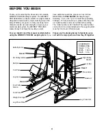
ASSEMBLED 
DIMENSIONS: 
Height: 77 in.
Width:

103 in. 

Depth:

55 in. 

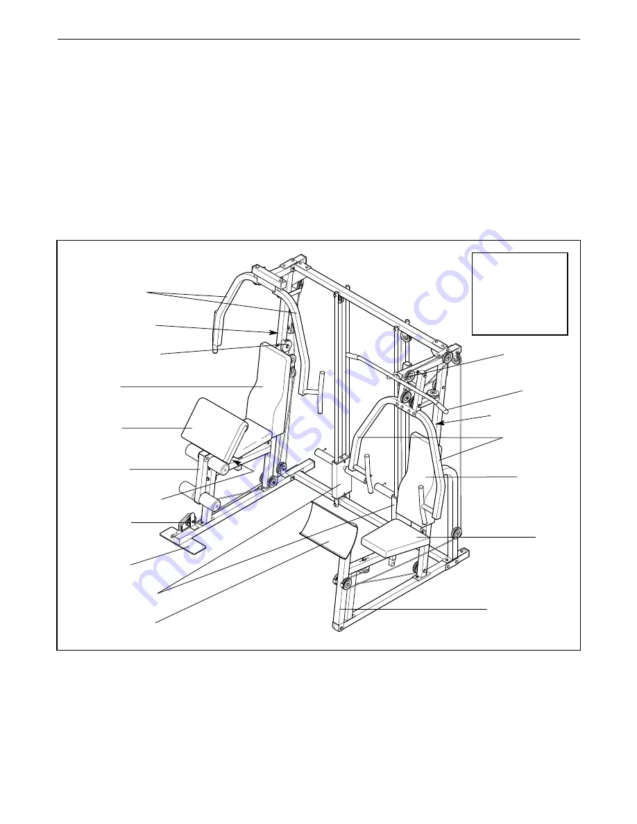
Low Pulley
Station

Foot Plate

Leg Lever

Press Arms

Decal 1

Decal 1

Decal 2

Backrest

Curl Pad

Butterfly Arms

Ab Pulley Station

Leg Press Arm

Thank you for selecting the innovative and versatile
WEIDER

®

PRO 9950 weight system. The WEIDER

®

PRO 9950 offers a unique selection of weight stations
designed to develop every major muscle group of the
body. Whether your goal is to tone your body, build
dramatic muscle size and strength or improve your
cardiovascular system, the WEIDER

®

PRO 9950

makes it easy to achieve the results you want.

For your benefit, read this manual carefully before
using the WEIDER

®

PRO 9950 weight system. 

If you

have additional questions, please call our toll-free
HELPLINE at 

1-800-736-6879

, Monday through

Saturday, 7 a.m. until 7 p.m. Central Time (excluding
holidays). To help us assist you, please note the prod-
uct model number and serial number before calling.
The model number is 831.159530. The serial number
can be found on a decal attached to the weight system
(see the front cover of this manual).

Please use the drawing below to familiarize your-
self with the major parts and how they fit together.

Leg Press Plate

Weight Carriage

Backrest

Seat

High Pulley

Station

Lat Bar

BEFORE YOU BEGIN

Summary of Contents for 831.159530

Page 1: ...r in the space above CAUTION Read all precautions and instruc tions in this manual before using this equipment Save this manu al for future reference Serial Number Decal Patent Pending Visit our websi...

Page 2: ...SHOOTING AND MAINTENANCE 27 ORDERING REPLACEMENT PARTS Back Cover FULL 90 DAY WARRANTY Back Cover Note A PART LIST EXPLODED DRAWING and a PART IDENTIFICATION CHART are attached in the center of this...

Page 3: ...ly arms leg lever lat bar or ab strap while weights are raised The weights will fall with great force 13 Always disconnect the lat bar or ab strap from the weight system when performing an exercise th...

Page 4: ...ER PRO 9950 makes it easy to achieve the results you want For your benefit read this manual carefully before using the WEIDER PRO 9950 weight system If you have additional questions please call our to...

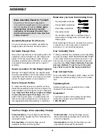
Page 5: ...f time and by deciding to make the task enjoyable assembly will go smoothly You may want to assemble the weight system over a couple of evenings Select a Location for the Weight System Because of its...

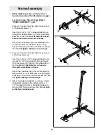
Page 6: ...nuts yet 2 Press a 2 Square Inner Cap 59 into each end of the Press Base 3 Insert four 5 16 x 2 1 2 Carriage Bolts 54 and two 3 8 x 2 1 2 Carriage Bolts 76 up through the Press Base 3 Place the Press...

Page 7: ...will be using Olympic weights with the weight system slide a Weight Sleeve 27 onto each end of the weight tube on the Weight Carriage 28 Secure each Weight Sleeve with a Locking Pin 31 Note The drawi...

Page 8: ...t 74 Do not tighten the Nylon Locknuts yet 8 8 7 Slide a Weight Carriage 28 onto each set of Weight Guides 33 Be sure the weight tubes are near the top of the Weight Carriages 7 33 33 5 89 58 58 28 28...

Page 9: ...64 59 12 Attach a Bumper 71 to the Press Seat Frame 12 with a Bumper Screw 72 Attach the Press Seat Frame 12 to the 5 16 x 2 1 2 Carriage Bolts 54 in the Press Base 3 with two 5 16 Nylon Locknuts 64 A...

Page 10: ...ght Butterfly Arm Assemble the Left Butterfly Arm 17 in the same manner 17 59 60 18 99 99 Handle 60 9 17 Lubricate both axles on the Butterfly Top Frame 19 Slide the Right Butterfly Arm 18 onto the in...

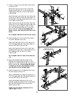
Page 11: ...Press Frame must be able to pivot easily 20 Attach the Right Press Arm 16 to the Press Frame 14 with two 5 16 x 2 1 2 Bolts 63 and two 5 16 Nylon Locknuts 64 Attach the Left Press Arm 15 in the same m...

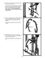
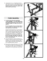
Page 12: ...her Wrap the Press Cable around a 3 1 2 Pulley 37 Attach the Pulley to the Press Top Frame 13 with a 3 8 x 3 1 2 Bolt 65 a 3 8 Washer 75 and a 3 8 Nylon Locknut 74 Be sure the Cable is between the Pul...

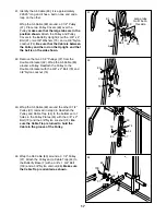
Page 13: ...e bottom of the Press Upright 6 with a 3 8 x 3 3 4 Bolt 62 a 3 8 Washer 75 and a 3 8 Nylon Locknut 74 Make sure the Cable Trap is turned to hold the Cable in the groove of the Pulley 28 80 44 74 75 62...

Page 14: ...p 44 to the 3 8 x 5 Bolt 61 with a 3 8 Nylon Locknut 74 Be sure the Cable Trap is turned to hold the Cable in the groove of the Pulley Do not tighten the Nylon Locknut yet 29 44 44 61 22 74 80 74 104...

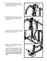
Page 15: ...e 3 8 x 2 1 2 Bolt 78 from the top of the indicated Weight Carriage 28 Attach the end of the Press Cable 80 to the Weight Carriage with the Bolt 78 and 3 8 Nylon Locknut 74 36 Identify the Butterfly C...

Page 16: ...ith a 3 8 x 2 Bolt 79 and a 3 8 Nylon Locknut 74 Be sure the Cable Trap is turned to hold the Cable in the groove of the Pulley 38 44 37 74 79 81 39 Wrap the Butterfly Cable 81 around a V Pulley 38 At...

Page 17: ...n 42 Remove the two 3 1 2 Pulleys 37 from the Double U bracket 42 Wrap the Ab Cable 83 around a Pulley Reattach the Pulley to the Double U bracket with the 3 8 x 2 Bolt 79 and 3 8 Nylon Locknut 74 43...

Page 18: ...83 to the indicat ed Weight Carriage 28 with a 3 8 x 2 1 2 Bolt 78 and a 3 8 Nylon Locknut 74 47 83 78 28 74 48 Identify the Leg Lever Cable 82 It is approxi mately 142 75 long and it has a ball on on...

Page 19: ...he bottom of the Double U bracket 42 with the 3 8 x 2 Bolt 79 and the 3 8 Nylon Locknut 74 37 79 82 42 74 51 Wrap the Leg Press Cable 82 around a 3 1 2 Pulley 37 Attach the Pulley and a Cable Trap 44...

Page 20: ...until tight 53 93 57 70 90 11 84 106 100 70 84 98 10 25 54 Attach the Butterfly Backrest 53 to the Butterfly Upright 4 with two 1 4 x 2 3 4 Screws 94 and two 1 4 Washers 84 54 53 4 84 84 55 Press a 1...

Page 21: ...he Leg Lever 8 Slide two Foam Pads 41 onto the ends of the Pad Tube 56 Press a 1 1 2 Square Inner Cap 100 into the back of the Backrest Bracket 21 Press two 1 x 2 Inner Caps 70 into the top and bottom...

Page 22: ...ing the weight system pull each cable a few times to make sure that the cables move smoothly over the pulleys If one of the cables does not move smoothly find and correct the problem Refer to the CABL...

Page 23: ...y tightened each time you use the weight system Replace any worn parts immediate ly The weight system can be cleaned with a damp cloth and a mild non abrasive detergent Do not use solvents 23 ADJUSTIN...

Page 24: ...en the Lat Bar and the Cable with two Cable Clips Adjust the length of the Chain between the Cable and the Lat Bar so that the Lat Bar is in the correct starting position for the exercise to be perfor...

Page 25: ...35 140 210 158 308 64 182 157 160 240 180 352 73 208 180 180 270 205 396 82 234 202 200 300 225 440 92 260 225 The chart below shows the approximate weight resistance at each exercise station Note The...

Page 26: ...e Make sure that the Cables are routed correctly that the pulleys move smoothly and that the cable traps do not touch or bind the Cables Incorrect cable routing can damage the weight system Leg Lever...

Page 27: ...cables To move a 3 1 2 Pulley 37 remove the 3 8 Nylon Locknut 74 and the 3 8 x 2 Bolt 79 from the Pulley Cable Trap 44 and Pulley Plates 43 Re attach the Pulley and Cable Trap to the appropriate adju...

Page 28: ...t SEARS Service Center To request service or to order parts by telephone call the toll free numbers listed at the left When requesting help or service or ordering parts please be pre pared to provide...

Page 29: ...s bag REMOVE THIS PART IDENTIFICATION CHART FROM THE MANUAL This chart is provided to help you identify the small parts used in assembly The number in parenthesis below each part refers to the key num...

Page 30: ...1 Retainer 85 1 CoverCap 86 1 3 4 Square Inner Cap 60 1 Inner Cap 32 1 x 2 Inner Cap 70 1 1 2 Round Inner Cap 67 3 4 Round Inner Cap 73 2 Square Inner Cap 59 1 1 2 Square Inner Cap 100...

Page 31: ...rew 98 5 16 Nylon Locknut 64 3 8 x 2 Bolt 79 3 8 x 1 Bolt 97 1 4 Nylon Locknut 106 5 16 x 2 1 2 Bolt 63 3 8 x 1 3 4 Bolt 103 3 8 x 2 1 2 Bolt 78 3 8 x 5 Bolt 61 3 8 x 6 Bolt 89 1 4 x 1 3 4 Carriage Bo...

Page 32: ...lt 62 3 8 x 9 Bolt 92 5 16 Washer 66 5 16 x 2 3 4 Bolt 55 3 8 x 3 1 4 Bolt 101 3 8 x 4 Bolt 91 3 8 x 4 1 4 Bolt 104 5 16 x 2 1 2 Carriage Bolt 54 3 8 x 2 1 2 Carriage Bolt 76 1 2 x 3 1 2 Bolt 96 3 8 x...

Page 33: ...81 REMOVE THIS PART LIST EXPLODED DRAWING FROM THE MANUAL...

Page 34: ...per 57 3 Support Plate 58 4 3 8 x 2 3 4 Bolt 59 12 2 Square Inner Cap 60 9 1 3 4 Square Inner Cap 61 2 3 8 x 5 Bolt 62 4 3 8 x 3 3 4 Bolt 63 6 5 16 x 2 1 2 Bolt 64 32 5 16 Nylon Locknut 65 3 3 8 x 3 1...

Page 35: ...37 74 37 75 65 32 68 32 44 37 74 90 106 84 21 57 90 93 84 98 74 64 26 58 74 89 37 79 5 74 64 26 58 37 74 89 79 78 38 50 74 78 38 50 64 74 74 75 49 37 49 94 84 83 75 91 4 94 84 55 66 64 44 37 74 64 44...

Reviews: