background image

5

ASSEMBLY

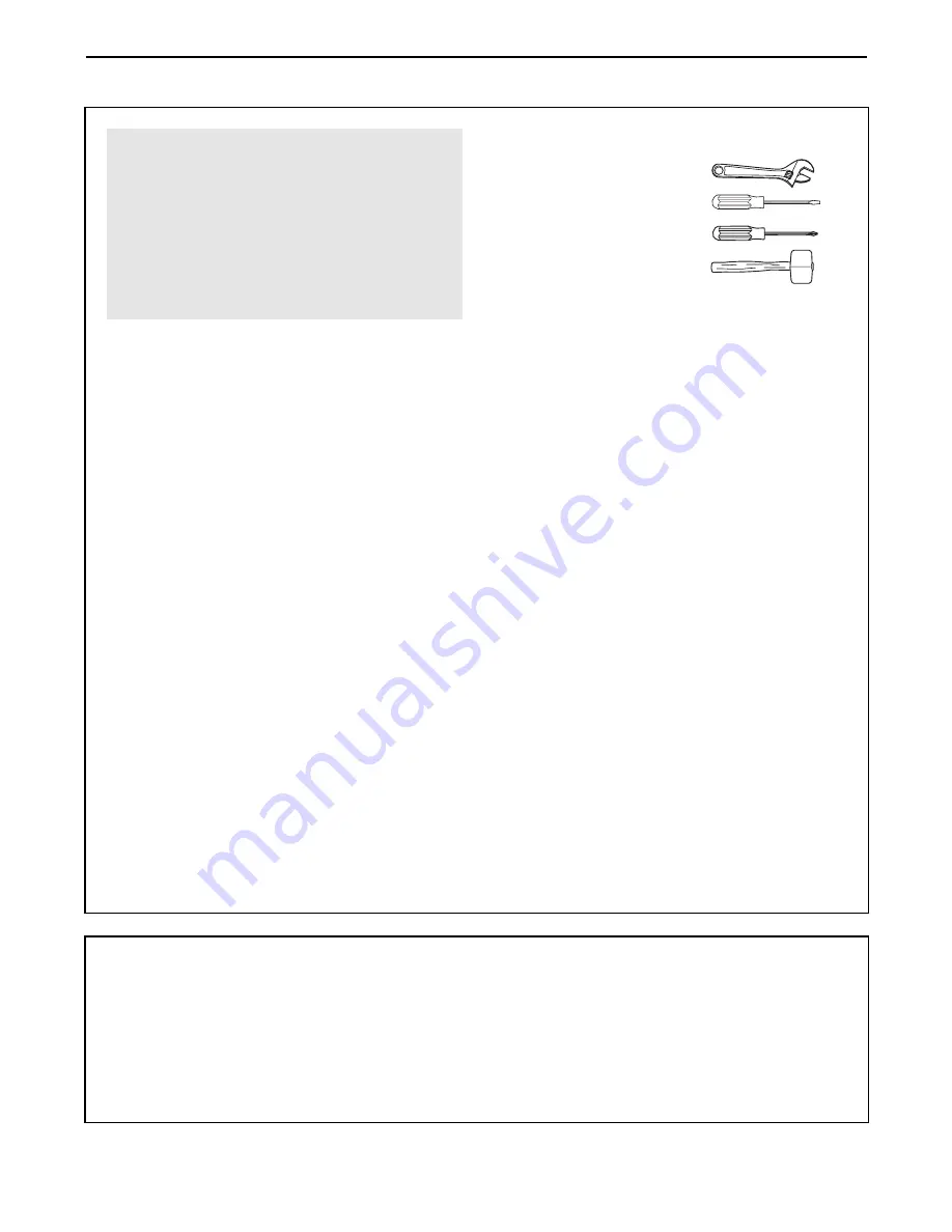
Make sure you have the following tools:

¥  Two (2) adjustable wrenches

¥  One (1) standard screwdriver

¥  One (1) phillips screwdriver

¥  One (1) rubber mallet

¥ You will also need grease or petroleum jelly, a

small amount of soapy water, and clear tape or
masking tape.

Note: Assembly will be more convenient if you have
a socket set, a set of open-end or closed-end
wrenches, or a set of ratchet wrenches.

How to Identify Parts

To help you identify the small parts used in assembly,
we have included a PART IDENTIFICATION CHART
in the center of this manual. Place the chart on the
floor and use it to easily identify parts during each
assembly step. 

Note: Some small parts may have

been pre-attached. If a part is not in the parts
bag, check to see if it has been pre-attached. 

How to Orient Parts

As you assemble the training system, make sure
that all parts are oriented exactly as shown in the
drawings. 

Tightening Parts

Tighten all parts as you assemble them, unless
instructed to do otherwise. 

Questions?

If you have questions after reading the assembly
instructions, please call our Customer Service
Department toll-free at 

1-800-999-3756

, Monday

through Friday, 6 a.m. until 6 p.m. Mountain Time.

Assembly Requires Two Persons

For your convenience and safety, assemble the
training system with the help of another person.

Set Aside Enough Time

Due to the many features of the training system,
the assembly process will require about six hours.
By setting aside plenty of time and by deciding to
make the task enjoyable, assembly will go smoothly.
You may want to assemble the training system over
a couple of evenings.

Select a Location for the Training
System

Because of its weight and size, the training system
should be assembled in the location where it will be
used. Make sure that there is enough room to walk
around the training system as you assemble it.

How to Unpack the Box

To make assembly as easy as possible, we have
divided the assembly process into four stages. The
parts needed for each stage are found in individual
bags. 

Important: Wait until you begin each stage

to open the parts bag for that stage. 

Place all

parts of the training system in a cleared area and
remove the packing materials. Do not dispose of
the packing materials until assembly is completed.

Make Assembly Easier for Yourself!

Everything in this manual is designed to
ensure that the training system can be
assembled successfully by anyone. 

Before

beginning assembly, make sure to read the
information on this page. This brief intro-
duction will save you much more time than
it takes to read it! 

The Four Stages of the Assembly Process

Frame AssemblyÑ

You will begin by assembling

the base and the uprights that form the skeleton of
the training system. 

Arm AssemblyÑ

During this stage you will

assemble the arms and the leg lever.

Cable Assembly

ÑDuring this stage you will

attach the cables and pulleys that connect the
arms to the weights. 

Seat AssemblyÑ

During the final stage you will

assemble the seats and the backrests.

Summary of Contents for 9300 PRO

Page 1: ...INE The trained techni cians on our customer hot line will provide immediate assis tance free of charge to you CUSTOMER HOT LINE 1 800 999 3756 Mon Fri 6 a m 6 p m MST Model No WESY29100 Serial No Wri...

Page 2: ...ranty does not extend to any product or damage to a product caused by or attributable to freight damage abuse misuse improper or abnormal usage or repairs not provided by an ICON authorized service ce...

Page 3: ...on the pul leys at all times If the cables bind while you are exercising stop immediately and make sure that the cables are on all of the pulleys 11 If you feel pain or dizziness at any time while exe...

Page 4: ...nd strength or improve your cardiovascular system the WEIDER 9300 PRO will help you to achieve the specific results you want For your benefit read this manual carefully before using the WEIDER 9300 PR...

Page 5: ...ess will require about six hours By setting aside plenty of time and by deciding to make the task enjoyable assembly will go smoothly You may want to assemble the training system over a couple of even...

Page 6: ...ress Upright 4 onto the indicated 5 16 x 2 1 2 Carriage Bolts 49 in the Press Base 13 Hand tighten two 5 16 Nylon Locknuts 40 onto the Carriage Bolts Do not tighten the Nylon Locknuts yet 3 Press two...

Page 7: ...shers 20 and two 5 16 Nylon Locknuts 40 Do not tighten the Nylon Locknuts yet 6 Insert two Weight Guides 23 into one of the brackets on the Weight Base 14 Attach the lower end of the Weight Guides wit...

Page 8: ...bricate the insides of the holes in the Top Weights 24 as shown Slide a Top Weight onto each set of Weight Guides 23 10 Attach the Top Frame 2 to the Ab Upright 1 with two 5 16 x 2 3 4 Bolts 55 two 5...

Page 9: ...two 1 2 x 3 4 Spacers 69 and a 5 16 Nylon Locknut 40 Do not over tighten the Nylon Locknut Before continuing firmly tighten all nylon locknuts used in steps 1 through 12 13 Locate and open the parts...

Page 10: ...eft Arm 6 Slide the Left Fly Arm onto the indicated axle Note Be careful not to confuse the Left Arm with the Right Arm 5 Be sure that the upper end of the Left Arm is behind the indicated bracket on...

Page 11: ...pproxi mate length of each Cable in inches is listed after the key number in the drawing IMPORTANT While assembling the cables do not over tighten the bolts and nuts attaching the pulleys The pulleys...

Page 12: ...lt 50 and the 3 8 Nylon Locknut not shown 22 Wrap the Butterfly Cable 88 around a 3 1 2 Pulley 82 as shown Attach the Pulley and a Cable Trap 80 to the other side of the bracket on the Press Upright 4...

Page 13: ...83 and the 3 1 2 Pulley 82 Be sure that the Cable is in the groove of the Pulley and that the Cable and Pulley move smoothly 26 Wrap the Rear Cable 86 around a 3 1 2 Pulley 82 Attach the Pulley to th...

Page 14: ...87 under the cross bar on the Press Frame 12 Wrap the Press Cable around a V Pulley 81 Attach the V Pulley to the lower bracket on the Press Upright 4 with a 3 8 x 2 1 4 Bolt 71 and a 3 8 Nylon Jam N...

Page 15: ...3 1 2 Bolt 66 33 Route the Press Cable 87 around a 3 1 2 Pulley 82 Attach the Pulley and a Cable Trap 80 to the Press Upright 4 with a 3 8 x 3 3 4 Bolt 76 a 3 8 Washer 38 and a 3 8 Nylon Jam Nut 43 Be...

Page 16: ...37 and a 1 4 Nylon Locknut 44 Do not completely tighten the Nylon Locknut It should be threaded onto the end of the Cable so only a couple of threads are showing above the Nylon Locknut as shown in th...

Page 17: ...1 4 Washer 37 and a 1 4 Nylon Locknut 44 Do not completely tighten the Nylon Locknut It should be threaded onto the Cable enough to be secure as shown in the inset drawing Attach the Small U Bracket 3...

Page 18: ...Pulley Reattach the Pulley and the Cable Trap to the lowest hole in the Pulley Plates with the Bolt and the Nylon Locknut Make sure that the Cable Trap is turned to hold the Cable in place 45 Wrap the...

Page 19: ...rame 16 with a 1 4 Washer 37 and a 1 4 x 2 Machine Screw 63 48 Press a 1 1 2 Square Inner Cap 57 into the Leg Lever 15 Lubricate the 5 16 x 2 1 4 Bolt 62 Attach the Leg Lever 15 to the Rear Seat Frame...

Page 20: ...78 into each Pad Tube 28 Insert a Pad Tube 28 into the Rear Seat Frame 16 Slide a Foam Pad 29 onto each end of the Pad Tube Insert the other Pad Tube 28 into the Leg Lever 15 Slide a Foam Pad 29 onto...

Page 21: ...hanged from 6 5 pounds to 106 5 pounds in increments of 12 5 pounds Note Due to the cables and pulleys the amount of resistance at each exercise station may vary from the weight setting Use the WEIGHT...

Page 22: ...e 85 with a Cable Clip 33 Attach the other end of the Chain to the Eyebolt 79 with a Cable Clip ADJUSTING THE CURL PAD Remove the Curl Post Knob 53 from the Curl Post 9 Align the holes in the Curl Fra...

Page 23: ...The actual resistance at each weight station may vary due to differences in indi vidual weight plates as well as friction between the cables pulleys and weight guides WEIGHT PRESS BUTTERFLY LEG HIGH L...

Page 24: ...e Cable Trap 80 3 1 2 Pulley 82 and Large U Bracket 83 Reattach the Pulley and Cable Trap to the lower hole in the Large U Bracket Be sure that the Cable Trap is in the proper position and that the Ca...

Page 25: ...hat the Cables have been assembled correctly The starting and ending points of each Cable have been labeled The numbers show the proper route for each Cable IMPORTANT If the Cables have not been cor r...

Page 26: ...26 High Cable 84 Rear Cable 86 Weight Stack 5 High Pulley 1 2 2 3 3 1 Top Frame 4 Weight Stack 4...

Page 27: ...27 NOTES...

Page 28: ...16 x 2 3 4 Bolt 55 5 16 x 3 Bolt 91 3 8 x 3 1 2 Bolt 66 1 4 Washer 37 5 16 Washer 20 3 8 Washer 38 1 4 Nylon Locknut 44 5 16 Nylon Locknut 40 5 16 Nylon Jam Nut 90 3 8 Nylon Locknut 42 1 Retainer 45...

Page 29: ...arriage Bolt 77 5 16 x 2 1 2 Carriage Bolt 49 1 4 x 2 1 2 Carriage Bolt 60 1 4 x 2 1 2 Machine Screw 64 1 4 x 2 Carriage Bolt 61 1 4 x 2 Machine Screw 63 V Pulley 81 Not shown to scale 3 1 2 Pulley 82...

Page 30: ...Square Outer Cap 58 1 3 4 Square Inner Cap 48 1 Round Outer Cap 46 1 1 2 Square Inner Cap 57 1 Round Inner Cap 70 1 x 7 8 Plastic Bushing 54 1 1 8 x 2 1 2 Plastic Bushing 47 3 4 Round Inner Cap 78 1...

Page 31: ...on Locknut 45 4 1 Retainer 46 2 1 Round Outer Cap 47 2 1 1 8 x 2 1 2 Plastic Bushing Key No Qty Description 48 6 1 3 4 Square Inner Cap 49 6 5 16 x 2 1 2 Carriage Bolt 50 12 3 8 x 2 Bolt 51 2 5 16 x 1...

Page 32: ...5 20 49 56 58 71 43 40 20 20 76 82 43 43 81 40 37 64 40 82 80 50 42 42 82 80 50 40 56 55 91 65 20 55 56 90 90 47 47 51 51 45 45 46 46 48 48 50 40 82 80 42 80 82 49 49 38 38 66 66 40 39 54 70 48 82 42...

Page 33: ...please be pre pared to give the following information 1 The MODEL NUMBER of the product WESY29100 2 The NAME of the product WEIDER 9300 PRO training system 3 The SERIAL NUMBER of the product see the...

Reviews: