background image

13

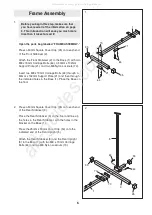
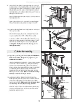
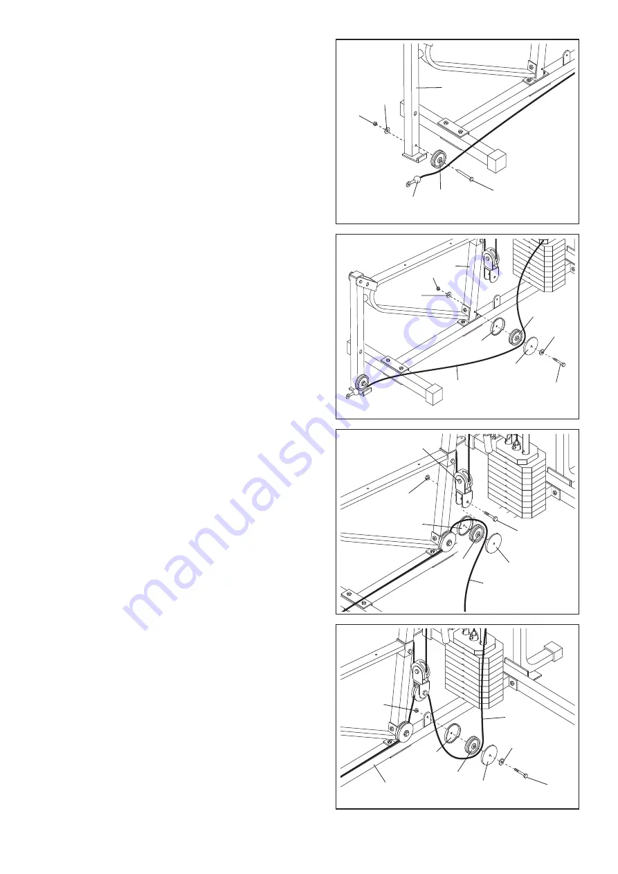
22. Identify the Low Cable (40), which is the only remain-

ing Cable. Note that there is a loop on one end of the

cable and a ball on the other.

Route the end of the Low Cable (40) with the ball

under a 90mm Pulley (50) as shown. Attach the

Pulley to the indicated hole in the Leg Lever (8) with

an M10 x 80mm Bolt (56), an M10 Flat Washer (62),

and an M10 Nylon Locknut (60).

Make sure that the

Cable is between the Pulley and the bracket on

the Leg Lever.

22

60

50

40

62

56

8

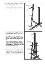
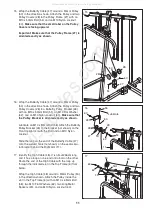
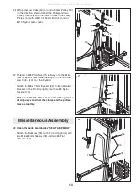
23. Wrap the Low Cable (40) around a 90mm Pulley (50)

in the direction shown. Attach the Pulley and two

Pulley Covers (28) to the indicated hole in the Front

Upright (4) with an M10 x 95mm Bolt (55), two M10

Flat Washers (62), and an M10 Nylon Locknut (60).

23

62

40

60

28

28

55

4

50

62

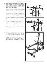
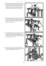
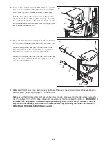
24. Wrap the Low Cable (40) around a 90mm Pulley (50)

in the direction shown. Attach the Pulley and two

Pulley Covers (28) to the lower half of the Pulley

Frame (27) with an M10 x 50mm Bolt (54) and an

M10 Nylon Locknut (60).

24

28

50

40

27

60

54

28

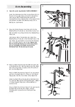
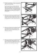
25. Wrap the Low Cable (40) around a 90mm Pulley (50)

in the direction shown. Attach the Pulley and two

Pulley Covers (28) to the indicated bracket on the

Base (1) with an M10 x 50mm Bolt (54), an M10 Flat

Washer (62), and an M10 Nylon Locknut (60).

25

28

50

60

62

28

1

54

40

All manuals and user guides at all-guides.com

Summary of Contents for powerguide x2

Page 1: ...or dam aged parts please call Or write ICON Health Fitness Ltd Unit 4 Revie Road Industrial Estate Revie Road Beeston Leeds LS118JG UK email csuk iconeurope com Serial Number Decal Patent Pending www...

Page 2: ...Chart 18 Maintenance and Trouble shooting 19 Part Identification Chart End of Manual Part List End of Manual Exploded Drawing End of Manual How to Order Replacement Parts Back Cover WEIDER is a regist...

Page 3: ...eights will fall with great force 12 Always disconnect the lat bar or row bar from the training system when performing an exercise that does not use them Do not leave the lat bar or row bar on the hig...

Page 4: ...achieve the results you want For your benefit read this manual carefully before using the WEIDER X2 If you have additional ques tions please call our Customer Service Department toll free at 08457 08...

Page 5: ...of time and by decid ing to make the task enjoyable assembly will go smoothly You may want to assemble the training system over a couple of evenings Select a Location for the Training System Because...

Page 6: ...a 50mm Square Cover Cap 35 onto each end of the Rear Stabiliser 3 Place the Rear Stabiliser 3 on the floor and line up the holes in the Rear Stabiliser with the holes in the bracket on the Base 1 Pre...

Page 7: ...he Weight Guides are turned so the indicated holes are at the top Slide the nine Weight Plates 36 onto the Weight Guides 13 Make sure that the Weight Plates are turned correctly the large grooves in t...

Page 8: ...5 60 57 6 37 64 21 13 4 5 70 6 Attach one Weight Guide 13 to the indicated brack et on the Top Frame 6 with an M8 x 38mm Bolt 67 an M8 Flat Washer 72 and an M8 Nylon Locknut 70 Attach the other Weigh...

Page 9: ...the side shown Do not overtighten the Nylon Locknut the Butterfly Press Frame must pivot easily 10 Press a 45mm Square Inner Cap 38 into each end of the Right Arm 11 Wet the lower end of the Right Ar...

Page 10: ...6 11 Insert the round tube on the Right Arm 11 into the indicated hole in the Butterfly Press Frame 9 While a second person holds the Right Arm place a 25mm Washer 85 over the tube on the Right Arm At...

Page 11: ...m Pulley 50 in the direction shown Attach the Pulley and two Pulley Covers 28 to the Pulley Frame 27 with an M10 x 50mm Bolt 54 and an M10 Nylon Locknut 60 Make sure that the small label on the Pulley...

Page 12: ...Pulley Covers 28 to the indicated holes in the Pulley Plates 25 with an M10 x 50mm Bolt 54 and an M10 Nylon Locknut 60 19 Slot 25 28 25 60 50 48 20 Wrap the High Cable 48 around a 90mm Pulley 50 in th...

Page 13: ...tach the Pulley and two Pulley Covers 28 to the indicated hole in the Front Upright 4 with an M10 x 95mm Bolt 55 two M10 Flat Washers 62 and an M10 Nylon Locknut 60 23 62 40 60 28 28 55 4 50 62 24 Wra...

Page 14: ...bles and the pulleys move smoothly 27 69 4 71 40 70 26 Wrap the Low Cable 40 around a 90mm Pulley 50 in the direction shown Attach the Pulley and two Pulley Covers 28 to the lowest holes in the Pulley...

Page 15: ...9 29 Insert an M6 x 38mm Carriage Bolt 74 into the centre hole in each Seat Plate 23 Attach each Seat Plate to the Seat 19 with two M6 x 15mm Screws 78 Turn the Seat 19 so the wide end is in the posit...

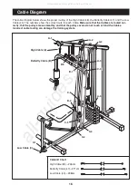
Page 16: ...are routed cor rectly that the pulleys move smoothly and that the pulley covers do not touch or bind the Cables Incorrect cable routing can damage the training system High Cable A Butterfly Cable B Lo...

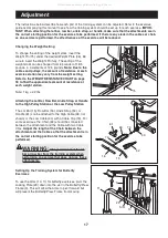
Page 17: ...the cables or chain as an exercise is performed the effectiveness of the exercise will be reduced 52 40 73 61 73 63 16 15 Changing the Weight Setting To change the setting of the weight stack insert t...

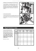
Page 18: ...t Guides 13 and secure the Locking Bar with the Lock 24 24 13 34 Holes The chart at the right shows the approximate weight resistance at each weight station Top refers to the 6 lb top weight the other...

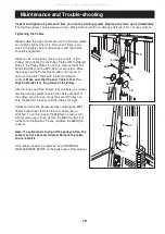
Page 19: ...ht If the cables are still loose move the second Pulley one hole Repeat this process until the cables are tight Additional slack can be removed by adjusting the M8 x 75mm Eyebolt 69 to which the Low C...

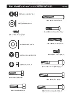
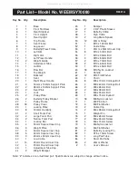
Page 20: ...m Screw 78 4 M6 x 65mm Screw 76 2 M6 x 38mm Carriage Bolt 74 2 M8 x 35mm Bolt 68 1 M8 Nylon Locknut 70 18 M8 Plain Nut 71 1 M8 x 38mm Bolt 67 2 M8 x 60mm Carraige Bolt 65 4 M8 x 65mm Bolt 66 2 M8 x 70...

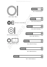
Page 21: ...m Bolt 58 2 M10 x 70mm Bolt 57 2 M10 x 80mm Bolt 56 3 M10 x 95mm Bolt 55 1 25mm Washer 85 2 M10 Nylon Locknut 60 18 M10 Flat Washer 62 12 M10 x 50mm Bolt 54 8 Long Metal Spacer 49 2 All manuals and us...

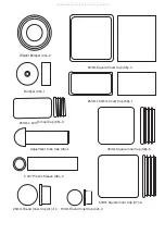
Page 22: ...x 50mm Inner Cap 39 3 50mm Square Cover Cap 35 4 25mm x 50mm Cover Cap 53 1 Weight Bumper 44 2 Adjustment Tube Cap 43 1 2 3 4 Plastic Sleeve 46 2 Bumper 45 1 45mm Square Inner Cap 38 5 50mm Square Inn...

Page 23: ...5 45mm Square Inner Cap 39 3 25mm x 50mm Inner Cap 40 1 Low Cable 41 14 25mm Round Inner Cap 42 4 19mm Round Inner Cap 43 1 Adjustment Tube Cap 44 2 Weight Bumper 45 1 Bumper 46 2 2 3 4 Plastic Sleev...

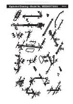
Page 24: ...28 46 11 31 38 38 10 46 38 69 60 57 70 60 58 62 39 62 66 80 76 76 70 60 62 71 40 44 36 75 43 14 48 13 70 70 68 17 67 72 41 73 51 62 81 39 62 60 41 85 37 81 9 41 85 37 77 41 22 65 30 41 20 70 41 30 47...

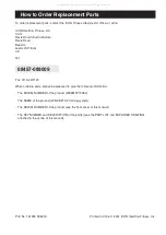
Page 25: ...be prepared to give the following information The MODEL NUMBER of the product WEEMSY70080 The NAME of the product WEIDER X2 training system The SERIAL NUMBER of the product see the front cover of thi...

Reviews: