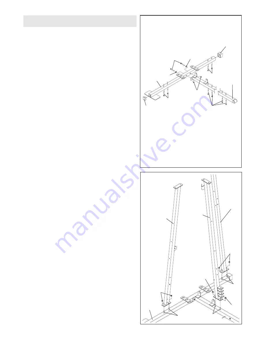
2.
Slide the Lat Upright (1) onto the indicated 5/16Ó x
2 1/2Ó Carriage Bolts (49) in the Weight Base (14).
Hand tighten two 5/16Ó Nylon Locknuts (40) onto the
Carriage Bolts.
Do not tighten the Nylon Locknuts
yet.
Slide the VKR Upright (51) onto the indicated 5/16Ó x
2 1/2Ó Carriage Bolts (49) in the Weight Base (14).
Hand tighten two 5/16Ó Nylon Locknuts (40) onto the
Carriage Bolts.
Do not tighten the Nylon Locknuts
yet.
Slide the Leg Press Upright (4) onto the indicated
5/16Ó x 2 1/2Ó Carriage Bolts (49) in the Press Base
(13). Hand tighten two 5/16Ó Nylon Locknuts (40) onto
the Carriage Bolts.
Do not tighten the Nylon
Locknuts yet.
5
Frame Assembly
1.
Before beginning assembly, make sure you have
read and understand the information in the box
above.
Locate and open the parts bags labeled ÒFRAME
ASSEMBLY BAG ONEÓ and ÒFRAME ASSEMBLY
BAG TWO.Ó
Press a 2Ó Square Outer Cap (58) onto the indicated
end of the Weight Base (14). Press a 2Ó Square Inner
Cap (56) into the indicated end of the Weight Base.
Insert four 5/16Ó x 2 1/2Ó Carriage Bolts (49) up
through the Weight Base (14) and place it flat on the
floor. Insert four 5/16Ó x 2 1/2Ó Carriage Bolts (49) up
through the Press Base (13) and place it on the floor
next to the Weight Base.
Attach the Press Base (13) to the Weight Base (14)
with two 5/16Ó x 2 3/4Ó Bolts (55), two 5/16Ó Washers
(20) and two 5/16Ó Nylon Locknuts (40).
Do not tight-
en the Nylon Locknuts yet.
1
56
58
55
20
20
49
40
49
13
14
49
2
1
4
40
40
40
49
49
13
14
49
40
51


