background image

3.

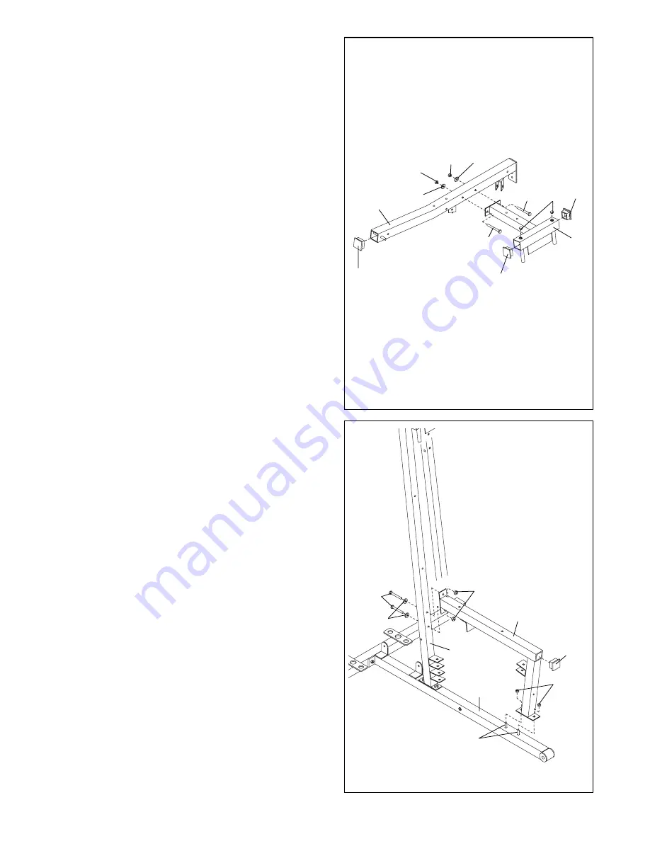
Press a 2Ó Square Inner Cap (56) into the end of the
Top Frame (2). Press a 2Ó Square Inner Cap (56) into
each side of the Butterfly Frame (3). Press two 1Ó
Round Inner Caps (70) into the top of the Butterfly
Frame. 

Insert a 5/16Ó x 3Ó Bolt (92) through the bracket on
the Butterfly Frame (3) and the Top Frame (2). 

Make

sure that the Bolt is on the side shown. 

Tighten a

5/16Ó Nylon Jam Nut (91) with a 5/16Ó Washer (20)
onto the Bolt.

Insert a 5/16Ó x 2 3/4Ó Bolt (55) through the bracket
on the Butterfly Frame (3) and the Top Frame (2).

Make sure that the Bolt is on the side shown.

Hand tighten a 5/16Ó Washer (20) and a 5/16Ó Nylon
Locknut (40) onto the Bolt.

4.

Slide the Front Seat Frame (8) onto the indicated
5/16Ó x 2 1/2Ó Carriage Bolts (49) in the Press Base
(13). Hand tighten two 5/16Ó Nylon Locknuts (40) onto
the Carriage Bolts.

Attach the other end of the Front Seat Frame (8) to
the Leg Press Upright (4) with two 5/16Ó x 2 3/4Ó Bolts
(55), two 5/16Ó Washers (20) and two 5/16Ó Nylon
Locknuts (40).

Press a 2Ó Square Inner Cap (56) into the  Front Seat
Frame (8).

3

6

2

3

55

40

20

56

56

56

92

70

91

20

4

55

20

49

40

56

8

40

4

13

Summary of Contents for Pro 9835

Page 1: ...T TO OUR TOLL FREE CUSTOMER HOT LINE The trained techni cians on our customer hot line will provide immediate assis tance free of charge to you CUSTOMER HOT LINE 1 800 999 3756 Mon Fri 6 a m 6 p m MST...

Page 2: ...foot plate when perform ing an exercise that could cause the home gym system to tip 8 Keep children under the age of 12 and pets away from the home gym system at all times 9 Keep hands and feet away...

Page 3: ...m the WEIDER PRO 9835 will help you to achieve the specific results you want For your benefit read this manual carefully before using the WEIDER PRO 9835 Home Gym System If you have additional questio...

Page 4: ...Unpacking the Box To make the assembly process as smooth as possi ble we have broken it into separate stages All parts used in each stage are found in individual packages in the shipping box Place all...

Page 5: ...Assembly 1 Before beginning assembly make sure you have read and understand the information in the box above Locate and open the parts bags labeled FRAME ASSEMBLY BAG ONE and FRAME ASSEMBLY BAG TWO Pr...

Page 6: ...t 55 through the bracket on the Butterfly Frame 3 and the Top Frame 2 Make sure that the Bolt is on the side shown Hand tighten a 5 16 Washer 20 and a 5 16 Nylon Locknut 40 onto the Bolt 4 Slide the F...

Page 7: ...in grooves in the upper Weights 6 26 25 90 90 5 Insert two Weight Guides 23 into each of the brack ets on the Weight Base 14 Slide a Weight Bumper 27 onto each of the Weight Guides 23 Slide eight Weig...

Page 8: ...rame 2 with two 5 16 x 2 3 4 Bolts 55 two 5 16 Washers 20 and two 5 16 Nylon Locknuts 40 Do not tighten the Nylon Locknuts yet 9 Attach the upper ends of one set of Weight Guides 23 to the Top Frame 2...

Page 9: ...o pivot the Leg Press Arm 12 Press a 1 x 7 8 Plastic Bushing 54 onto each welded spacer on the Press Frame 12 Slide the Press Frame onto the Press Base 13 so that the Plastic Bushings are aligned with...

Page 10: ...8 into the upper end of the Left Arm 6 Slide the Left Arm onto the indicated axle Note Be careful not to confuse the Left Arm with the Right Arm 5 Make sure the upper end of the Left Arm is behind the...

Page 11: ...the Cables by comparing the lengths and the ends The approxi mate length of each Cable in inches is listed after the key number in the drawing IMPORTANT While assembling the cables do not overtighten...

Page 12: ...x 2 Bolt 50 and the 3 8 Nylon Locknut 42 not shown 21 Wrap the Butterfly Cable 89 around a 3 1 2 Pulley 82 as shown Attach the Pulley and a Cable Trap 80 to the other side of the bracket on the Leg P...

Page 13: ...1 2 Pulley 82 Make sure the Cable is in the groove of the Pulley and that the Cable and Pulley move smoothly 25 Wrap the Rear Cable 87 around a 3 1 2 Pulley 82 Attach the Pulley to the Top Frame 2 wit...

Page 14: ...the Press Cable 88 around a 3 1 2 Pulley 82 Attach the Pulley and a Cable Trap 80 to the indicated bracket on the Press Base 13 with a 3 8 x 2 Bolt 50 and a 3 8 Nylon Locknut 42 Make sure the Cable T...

Page 15: ...a Cable Trap 80 to the Leg Press Upright 4 with a 3 8 x 3 1 2 Bolt 66 a 3 8 Washer 38 and a 3 8 Nylon Jam Nut 43 Make sure the Cable Trap 80 is turned to hold the Cable in place 32 Route the Press Cab...

Page 16: ...Cable 88 around a 3 1 2 Pulley 82 Attach the Pulley and a Cable Trap 80 to the Leg Press Arm 9 with the 3 8 x 4 1 2 Bolt 74 Slide another 3 1 2 Pulley 82 with a Cable Trap 80 onto the 3 8 x 4 1 2 Bol...

Page 17: ...olt but do not fully tighten it Leave enough room between the two Jam Nuts for the Cable to pivot 40 Locate the High Cable 85 this is the longest remaining cable Wrap the High Cable around a 3 1 2 Pul...

Page 18: ...be routed from the direction shown 44 Thread a 1 2 Plain Nut 35 onto the end of the High Cable 85 Place a 1 2 Washer 68 and a 1 1 4 x 1 2 Weight Spacer 10 on top of the Weight Tube 25 Thread the end o...

Page 19: ...he Bolt and the Nylon Locknut Make sure the Cable Trap is turned to hold the Cable in place 47 Wrap the Low Cable 86 around a 3 1 2 Pulley 82 Attach the Pulley to the Lat Upright 1 with the 3 8 x 3 1...

Page 20: ...ach the Leg Lever 15 to the Rear Seat Frame 16 with the Bolt and a 5 16 Nylon Locknut 40 Do not overtighten the Nylon Locknut the Leg Lever must pivot freely Insert the 5 16 x 2 Eyebolt 79 into the Le...

Page 21: ...Insert the 1 4 x 2 1 2 Carriage Bolt 60 through the indicated hole in the Front Seat Frame 8 Tighten a 1 4 Nylon Locknut 44 with a 1 4 Washer 37 onto the Carriage Bolt Attach the other end of the Seat...

Page 22: ...of this manual for proper cable routing If there is any slack in the cables you will need to remove the slack by tightening the cables See TROUBLE SHOOTING AND MAINTENANCE on page 25 56 40 92 40 32 5...

Page 23: ...Cable with two Cable Clips Adjust the length of the Chain between the Lat Bar and the High Cable so the Lat Bar is in the correct starting position for the exer cise to be performed The Handle 96 can...

Page 24: ...G LEVER TO THE LOW PULLEY STATION To use the Leg Lever 15 the seat must be attached to the front upright see ATTACHING AND REMOVING THE SEAT above Attach one end of the Chain 34 to the Low Cable 86 wi...

Page 25: ...er Pulley to the higher hole in the Pulley Plates without the Cable Trap Keep the Cable Traps for future use Make sure the Cable and Pulley move smoothly Do not overtighten the cables If the cables ar...

Page 26: ...e been assembled correctly The starting and ending points of each Cable have been labeled The numbers show the proper route for each Cable IMPORTANT If the Cables have not been cor rectly routed the h...

Page 27: ...8 5 148 103 58 80 80 263 6 175 120 68 96 91 310 7 205 143 76 107 101 358 8 240 173 90 123 120 410 This chart shows the approximate weight resistance at each station Top refers to the 6 5 lbs top weigh...

Page 28: ...0 50 42 42 82 80 50 40 56 55 92 70 98 55 56 91 91 47 47 95 95 45 45 46 46 48 48 50 40 82 80 42 80 82 49 49 75 38 38 94 94 40 39 54 70 48 82 43 80 52 81 42 40 82 91 53 72 73 59 83 65 37 44 56 64 37 60...

Page 29: ...are Inner Cap 49 8 5 16 x 2 1 2 Carriage Bolt 50 13 3 8 x 2 Bolt 51 1 VKR Upright 52 1 3 8 x 8 Bolt 53 1 Leg Press Bumper 54 2 1 x 7 8 Plastic Bushing 55 12 5 16 x 2 3 4 Bolt 56 10 2 Square Inner Cap...

Page 30: ...x 2 3 4 Carriage Bolt 77 5 16 x 2 1 2 Carriage Bolt 49 1 4 x 2 1 2 Carriage Bolt 60 1 4 x 2 1 2 Machine Screw 64 1 4 x 2 Carriage Bolt 61 1 4 x 2 Machine Screw 63 V Pulley 81 Not shown to scale 3 1 2...

Page 31: ...1 2 Bolt 39 3 8 x 2 1 2 Bolt 65 1 5 16 x 2 3 4 Bolt 55 5 16 x 3 Bolt 92 3 8 x 3 Bolt 94 3 8 x 3 1 2 Bolt 66 1 4 Washer 37 5 16 Washer 20 3 8 Washer 38 1 4 Nylon Locknut 44 5 16 Nylon Locknut 40 5 16...

Page 32: ...ner Cap 56 2 Square Outer Cap 58 1 3 4 Square Inner Cap 48 1 Round Outer Cap 46 1 1 2 Square Inner Cap 57 1 Round Inner Cap 70 3 4 Round Inner Cap 78 1 x 7 8 Plastic Bushing 54 1 1 8 x 2 1 2 Plastic B...

Page 33: ...oof of purchase All returns must be pre autho rized by ICON This warranty does not extend to any product or damage to a product caused by or attribut able to freight damage abuse misuse improper or ab...

Reviews: